Diagnostics
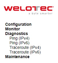
The Diagnostics menu is a collection of software tools that can be used to check the network connection for your managed switch. The submenus under the Diagnostics menu are shown in Figure 4.1. The available network diagnostic tools are Ping (IPv4), Ping (IPv6), Traceroute (IPv4), and Traceroute (IPv6).
Ping (IPv4)
Welotec’s managed switch provides a network tool called Ping for testing network connectivity in this subsection. Ping is a network diagnostic utility for testing reachability between a destination device and the managed switch. It utilizes ICMP (Internet Control Message Protocol) packet to troubleshoot IP connectivity issues. Note that this utility is only for IPv4 address. The Ping utility for IPv6 will be provided in the next subsection. Figure 4.2 shows the user interface for using the Ping command for IP version 4. The user must at least enter the Hostname or IP Address for the destination to be checked with Ping tool. Description of each parameter for Ping tool is summarized in Table 4.1.
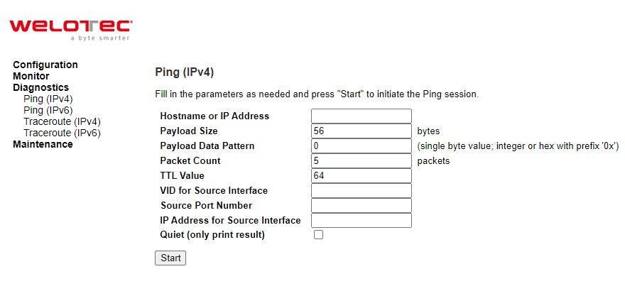
Table 4.1 Descriptions of Options for Ping (IPv4) Diagnostic Tool:
Label |
Description |
|---|---|
Hostname or IP Address |
The address of the destination host, either as a symbolic hostname or an IP Address. |
Payload Size |
Determines the size of the ICMP data payload in bytes (excluding the size of Ethernet, IP and ICMP headers). The default value is 56 bytes. The valid range is 2-1452 bytes. |
Label |
Description |
Payload Data Pattern |
Determines the data pattern used in the ICMP data payload in single byte value. The default value is 0. The valid range is 0-255. |
Packet Count |
Determines the number of PING requests (ICMP packets) to be sent to the destination. The default value is 5. The valid range is 1-60. |
TTL Value |
Determines the Time-To-Live (TTL) field value in the IPv4 header. This is the integer value to be set for the number of hops that the ping packet can traverse the network. If TTL reaches zero (deducted by a host after it reached a host), the ping packet will be discarded. The default value is 64. The valid range is 1-255. |
VID for source Interface |
This field can be used to force the Ping test to use a specific local VLAN interface as the source interface. Leave this field empty for automatic selection based on routing configuration. |
Source Port Number |
This field can be used to force the Ping test to use a specific local interface with the specified port number as the source interface. The specified port must be configured with a suitable IP address. Leave this field empty for automatic selection based on routing configuration. |
IP Address for Source Interface |
This field can be used to force the test to use a specific local interface with the specified IP address as the source interface. The specified IP address must be configured on a local interface. Leave this field empty for automatic selection based on routing configuration. |
Quiet (only print result) |
Checking this option will enable the quiet mode which only print the ping’s final results without the result of each ping request. |
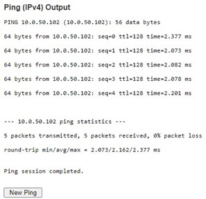
After the user enters an IP address or a domain name into the field to verify network connectivity. Click Start button to run the ping tool. After you press Start, ICMP packets are transmitted, and the sequence number and round-trip-time are displayed upon reception of a reply. The amount of data received inside of an IP packet of type ICMP ECHO_REPLY will always be 8 bytes more than the requested payload data size (the difference is the ICMP header). The page refreshes automatically until responses to all packets are received, or until a timeout occurs.
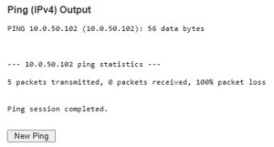
An example of successful ping to an IPv4 address is shown in Figure 4.3 while an example of a failure ping is depicted in Figure 4.4. Note that the user can initiate another ping command by clicking the New Ping button at the end of the Ping (IPv4) Output webpage.
Ping (IPv6)
This page allows you to issue ICMPv6 PING packets to troubleshoot IPv6 connectivity issues. The user can enter an IP address or a domain name into the Hostname or IP Address field to verify network connectivity for IP version 6 network as shown in Figure 4.5. After entering the IP address or hostname, click Start button to run the Ping (IPv6) function. An example of successful ping result is shown in Figure 4.6 while a failure ping result is depicted in Figure 4.6. Note that the user can initiate another ping command by clicking the New Ping button at the end of the Ping (IPv6) Output webpage. Description of each parameter for Ping (IPv6) tool is summarized in Table 4.2
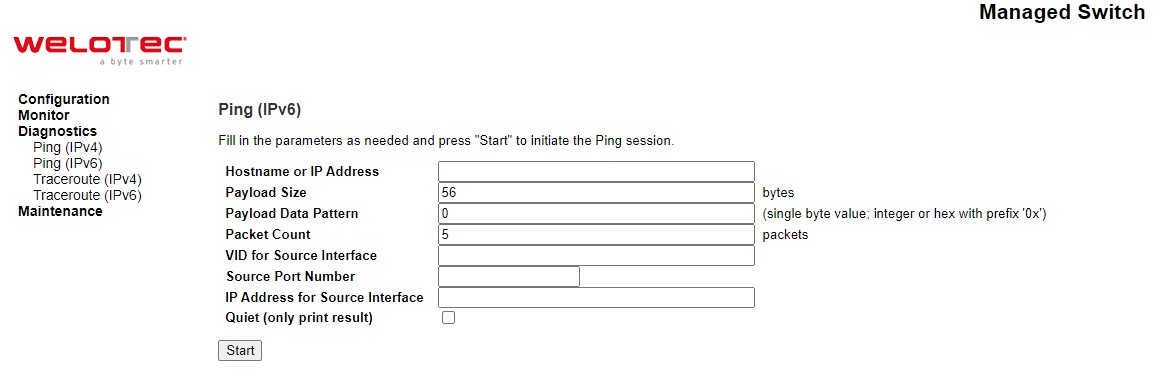
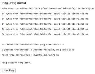
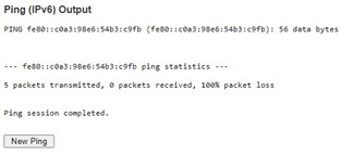
Table 4.2 Descriptions of Options for Ping (IPv6) Diagnostic Tool:
Label |
Description |
|---|---|
Hostname or IP Address |
The address of the destination host, either as a symbolic hostname or an IP Address. |
Payload Size |
Determines the size of the ICMP data payload in bytes (excluding the size of Ethernet, IP and ICMP headers). The default value is 56 bytes. The valid range is 2-1452 bytes. |
Payload Data Pattern |
Determines the data pattern used in the ICMP data payload in single byte value. The default value is 0. The valid range is 0-255. |
Packet Count |
Determines the number of PING requests (ICMP packets) to be sent to the destination. The default value is 5. The valid range is 1-60. |
VID for source Interface |
This field can be used to force the Ping test to use a specific local VLAN interface as the source interface. Leave this field empty for automatic selection based on routing configuration. |
Source Port Number |
This field can be used to force the Ping test to use a specific local interface with the specified port number as the source interface. The specified port must be configured with a suitable IP address. Leave this field empty for automatic selection based on routing configuration. |
IP Address for Source Interface |
This field can be used to force the test to use a specific local interface with the specified IP address as the source interface. The specified IP address must be configured on a local interface. Leave this field empty for automatic selection based on routing configuration. |
Quiet (only print result) |
Checking this option will enable the quiet mode which only print the ping’s final results without the result of each ping request. |
Traceroute (IPv4)
Traceroute (IPv4) is another diagnostic tool that allows the user to check the path or route that packets take from the managed switch to a destination host or IP address. This tool could provide information about host or gateway along the path to the specified destination. It can measure transit delays of packets across the IPv4 network. Figure 4.8 shows the webpage for Traceroute (IPv4) tool on the managed switch. Table 4.3 provides brief descriptions of all parameters on the webpage. The only required parameter to start the Traceroute (IPv4) is the Hostname or IP Address. An example of traceroute result is shown in Figure 4.9. Note that the user can initiate another traceroute command by clicking the New Traceroute button at the end of the Traceroute (IPv4) Output webpage.
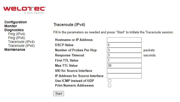
Table 4.3 Description of each parameter for Traceroute (IPv4):
Label |
Description |
|---|---|
Hostname or IP Address |
Specifies the hostname or IP Address of the destination |
DSCP Value |
Specifies the DSCP (DiffServ Code Point) priority (value) in packets. The value is an integer that has a range from 0 to 63. |
Number of Probes Per Hop |
Specifies the number of probe packets sent for each hop which is the number of queries per intermediate host or gateway. The default value is 3 packets. The valid range is 1 – 60. |
Response Timeout |
Specifies the timeout for the response message or ICMP echo reply after an ICMP echo request message is sent to an intermediate host or gateway. This is the number of seconds to wait for a reply to a sent request. The default number is 3. The valid range is 1 – 86400. |
First TTL Value |
Specifies the initial Time to Live (TTL) value. This is a field in the IPv4 header in the first packet sent. The default value is 1. The valid range is 1 – 30. |
Max TTL Value |
Specifies the maximum number of hops traceroute will try to probe. If this value is reached before the specified remote host is reached, the test stops. The default value is 30. The valid range is 1 – 255. |
VID for source Interface |
This field can be used to force the test to use a specific local VLAN interface as the source interface. Leave this field empty for automatic selection based on routing configuration. |
IP Address for Source Interface |
This field can be used to force the test to use a specific local interface with the specified IP address as the source interface. The specified IP address must be configured on a local interface. Leave this field empty for automatic selection based on routing configuration. |
Use ICMP instead of UDP |
By default, the traceroute command will use UDP datagrams. Selecting this option forces it to use ICMP ECHO packets instead. |
Print Numeric Addresses |
By default, the traceroute command will print out hop information using a reverse DNS lookup for the acquired host IP addresses. This may slow down the display if the DNS information is not available. Selecting this option will prevent the reverse DNS lookup and force the traceroute command to print numeric IP addresses instead. |
output.jpg)
Traceroute (IPv6)
Traceroute (IPv6) is another diagnostic tool that allows the user to check the path or route that packets take from the managed switch to a destination host or IP address in IP version 6 network. This tool could provide information about host or gateway along the path to the specified destination. It can measure transit delays of packets across the IPv6 network. Figure 4.10 shows the webpage for Traceroute (IPv6) tool on the managed switch. Table 4.4 provides brief descriptions of all parameters on this webpage.
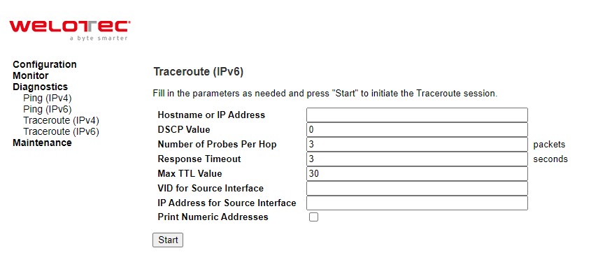
Table 4.4 Description of each parameter for Traceroute (IPv6):
Label |
Description |
|---|---|
Hostname or IP Address |
Specifies the hostname or IP Address of the destination |
DSCP Value |
Specifies the DSCP (DiffServ Code Point) priority in packets. The value is an integer that has a range from 0 to 255. |
Number of Probes Per Hop |
Specifies the number of probe packets sent for each hop which is the number of queries per intermediate host or gateway. The default value is 3 packets. The valid range is 1 – 60. |
Response Timeout |
Specifies the timeout for the response message or ICMP echo reply after an ICMP echo request message is sent to an intermediate host or gateway. Determines the number of seconds to wait for a reply to a sent request. The default number is 3. The valid range is 1- 86400. |
Max TTL Value |
Specifies the maximum number of hops traceroute will try to probe. If this value is reached before the specified remote host is reached, the test stops. The default number is 255. The valid range is 1-255. |
VID for source Interface |
This field can be used to force the test to use a specific local VLAN interface as the source interface. Leave this field empty for automatic selection based on routing configuration. |
IP Address for Source Interface |
This field can be used to force the test to use a specific local interface with the specified IP address as the source interface. The specified IP address must be |
Label |
Description |
configured on a local interface. Leave this field empty for automatic selection based on routing configuration. |
|
Print Numeric Addresses |
By default, the traceroute command will print out hop information using a reverse DNS lookup for the acquired host IP addresses. This may slow down the display if the DNS information is not available. Selecting this option will prevent the reverse DNS lookup and force the traceroute command to print numeric IP addresses instead. |