Monitor
The Welotec’s RSAES managed switch has an extensive set of status monitoring features on the WebUI. The user can select the submenus under the Monitor menu to check for the information or current status of the operations and protocols running on the Welotec’s RSAES managed switch. The following sections will describe each submenu under the Monitor menu.
System
Information
System information webpage shown in Figure 3.1 provides information of both hardware and software of the RSAES managed switch. Description of each field is explained in Table 3.1.
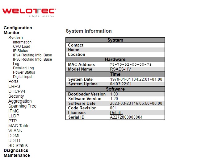
Table 3.1 Monitoring Descriptions of System Information:
Label |
Description |
Factory Default |
|---|---|---|
Contact |
The system contact configured in Configuration | System | Information | System Contact. |
Null |
Name |
The system name configured in Configuration | System | Information | System Name. |
Null |
Location |
The system location configured in Configuration | System | Information | System Location. |
Null |
MAC Address |
The MAC Address of this switch. |
DUT’s MAC address |
Model Name |
The Chip ID of this switch. |
Ex: RSAESs-3SFP-DC |
System Date |
The current (GMT) system time and date. The system time is obtained through the Timing server running on the switch, if any. |
DUT’s current time |
System Uptime |
The period of time the device has been operational. |
DUT’s bootup time |
Bootloader Version |
Version of firmware. |
DUT’s bootloader version |
Software Version |
The software version of this switch. |
DUT’s firmware version |
Software Date |
The date when the switch software was produced. |
DUT’s firmware builded time |
Code Revision |
The version control identifier of the switch software. |
001 |
Licenses |
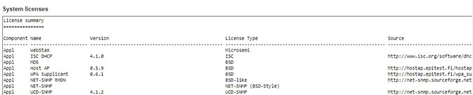
Summary of the software license e.g., component, name, version, license type, and source. |
Check the Auto-refresh box to refresh the page automatically. The automatic refresh occurs every 3 seconds. Otherwise, click Refresh box to refresh the page immediately.
After Clicking Licenses, users will be directed to the summary of software license as shown in Figure 3.2.
CPU Load
This page displays the CPU load, using an SVG graph. The load is measured as averaged over the last 100ms, 1sec and 10 seconds intervals. The last 120 samples are graphed, and the last numbers are displayed as text as well. In order to display the SVG graph, your browser must support the SVG format. Consult the SVG Wiki for more information on browser support. Specifically, at the time of writing, Microsoft Internet Explorer will need to have a plugin installed to support SVG.
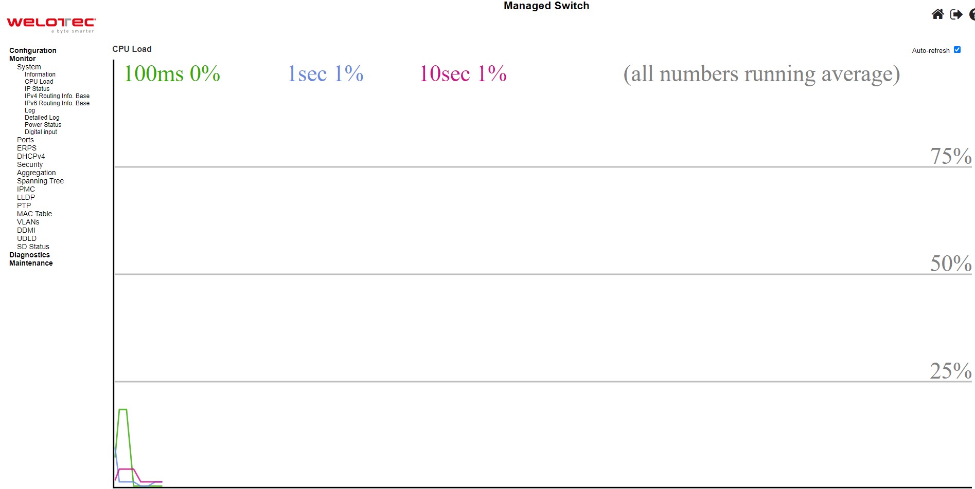
Check the Auto-refresh box to refresh the page automatically. The automatic refresh occurs every 3 seconds.
IP Status
This page displays the status of the IP protocol layer. The status is defined by the IP interfaces, the IPv6 routes and the neighbour cache (ARP cache) status.
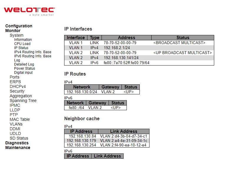
Table 3.2 Monitor Descriptions of System’s IP Status:
Label |
Description |
Factory Default |
|---|---|---|
IP Interfaces |
||
Interface |
The name of the interface. |
VLAN 1 |
Type |
The address type of the entry. This may be LINK, IPv4, IPv6. |
LINK, IPv4, IPv6 |
Address |
The current address of the interface (of the given type). |
DUT’s MAC address/ IPv4 address/ IPv6 address |
Status |
The status flags of the interface (and/or address). |
<UP BROADCAST MULTICAST> |
IP Routes |
||
Network |
The destination IPv4/IPv6 network or host address of this route. |
10.0.50.0/24, fe80::/64 |
Gateway |
The gateway address of this route. |
VLAN 1 |
Status |
The status flags of the route. |
<UP> |
Neighbour cache |
||
IP Address |
The IPv4/IPv6 address of the entry. |
- |
Link Address |
The Link (MAC) address for which a binding to the IP address given exist. |
- |
Check the Auto-refresh box to refresh the page automatically. The automatic refresh occurs every 3 seconds.
IPv4 Routing Info. Base
This table in Figure 3.5 provides IPv4 routing status. Each page shows up to 999 table entries, selected through the “entries per page” input field. When first visited, the webpage will show the beginning entries of this table. The “Start from ID” input field allow the user to change the starting point in this table. Clicking the Refresh button will update the displayed table starting from that or the closest next entry match. In addition, the input fields on the webpage will upon a Refresh button click - assume the value of the first displayed entry, allowing for continuous refresh with the same start input field. Table 3.3 summarizes the description of each label in Routing Information Base webpage.
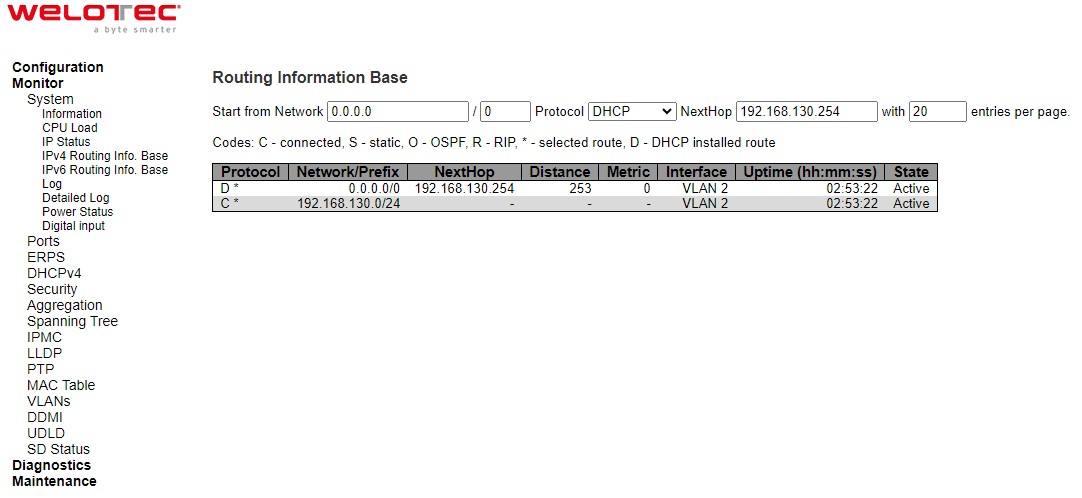
Table 3.3 Monitoring Descriptions of System’s IPv4 Routing Information Base:
Label |
Description |
|---|---|
Protocol |
The protocol that installed this route. |
Network/Prefix |
Network and prefix (example 192.168.2.1/24) of the given route entry |
NextHop |
Next-hop IP address. All-zeroes indicates the link is directly connected |
Interface |
Next-hop interface. |
Distance |
Distance of the route |
Metric |
Metric of the route |
Uptime (hh:ss:mm) |
Time (in seconds) since this route was created |
State |
Destination is active |
Click Refresh button to refresh the page immediately. Check the autorefresh-box to refresh the page automatically.
Automatic refresh occurs every 3 seconds. |<<: Updates the table entries, starting from the first available entry. If the first entry of the table is displayed, the button is disabled. <<: Updates the table entries, ending at the entry prior to the first entry currently displayed. If the first entry of the table is displayed, the button is disabled. >>: Updates the table entries, starting from the entry next to the last entry currently displayed. If the last entry of the table is displayed, the button is disabled. >>|: Updates the table entries, ending at the last available entry. If the last entry of the table is displayed, the button is disabled.
IPv6 Routing Info. Base
This table in Figure 3.6 provides IPv6 routing status. Each page shows up to 999 table entries, selected through the “entries per page” input field. When first visited, the web page will show the beginning entries of this table. The “Start from ID” input field allow the user to change the starting point in this table. Clicking the Refresh button will update the displayed table starting from that or the closest next entry match. In addition, these input fields will upon a Refresh button click - assume the value of the first displayed entry, allowing for continuous refresh with the same start input field. Table 3.4 summarizes the description of each label in Routing Information Base webpage.
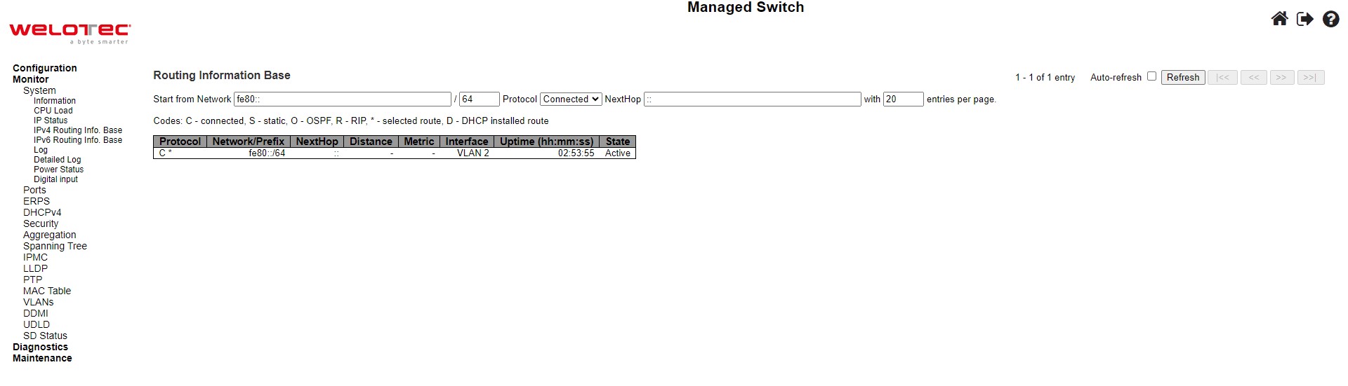
Table 3.4 Monitoring Descriptions of System’s IPv6 Routing Information Base:
Label |
Description |
|---|---|
Protocol |
The protocol that installed this route. |
Network/Prefix |
Network and prefix (example 10.0.0.0/16) of the given route entry. |
NextHop |
Next-hop IP address. All-zeroes indicates the link is directly connected. |
Distance |
Distance of the route. |
Metric |
Metric of the route. |
Interface |
If the next-hop address is a link-local address, then this is the VLAN interface of the linklocal address. Otherwise, this value is not used. |
Uptime (hh:ss:mm) |
Time (in seconds) since this route was created |
State |
Destination is active |
Click Refresh button to refresh the page immediately. Check this autorefresh-box to refresh the page automatically.
Automatic refresh occurs every 3 seconds. |<<: Updates the table entries, starting from the first available entry. If the first entry of the table is displayed, the button is disabled. <<: Updates the table entries, ending at the entry prior to the first entry currently displayed. If the first entry of the table is displayed, the button is disabled. >>: Updates the table entries, starting from the entry next to the last entry currently displayed. If the last entry of the table is displayed, the button is disabled. >>|: Updates the table entries, ending at the last available entry. If the last entry of the table is displayed, the button is disabled.
Log
The managed switch’s system log information is provided in this Log webpage shown in Figure 3.7. Each page can display up to 999 table entries which can be selected through the “entries per page” input field. When first visited, the web page will show the beginning entries of this table. The “Level” input field is used to filter the display system log entries. The “Clear Level” input field is used to specify which system log entries will be cleared. To clear specific system log entries, select the clear level first then click the Clear button.
The “Start from ID” input field allows the user to change the starting point in this table. Clicking the Refresh button will update the displayed table starting from that or the closest next entry match. In addition, these input fields will upon a Refresh button click - assume the value of the first displayed entry, allowing for continuous refresh with the same start input field.
The >> will use the last entry of the currently displayed table as a basis for the next lookup. When the end is reached the text “No more entries” is shown in the displayed table. Use the >>| button to start over.
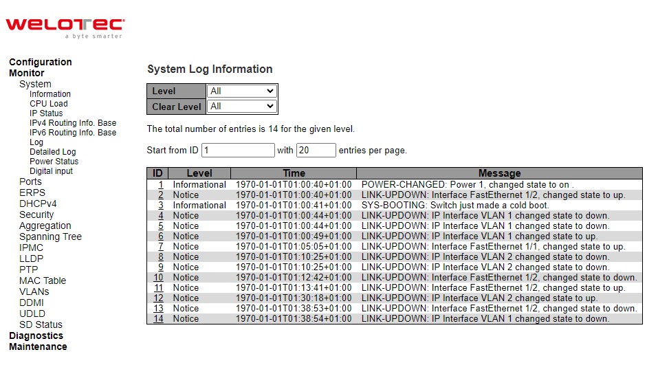
Table 3.5 Monitoring Descriptions of System Log:
Label |
Description |
|---|---|
ID |
The identification of the system log entry |
Level |
The level of the system log entry |
Time |
The occurred time of the system log entry |
Message |
The detail message of the system log entry |
Detailed Log
The managed switch system detailed log information is provided in this webpage shown in Figure 3.8. Table 3.6 provides descriptions for the Detailed System Log Information.
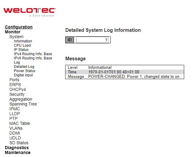
Table 3.6 Monitoring Descriptions of System Detailed Log:
Label |
Description |
|---|---|
Level |
The severity level of the system log entry. |
ID |
The ID (>= 1) of the system log entry |
Message |
The detail message of the system log entry |
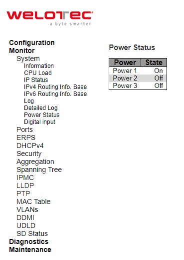
Power Status
This webpage in Figure 3.9 shows Power Status of the device. There are two or three powers: Power1, Power 2, and Power3, and the power state can be either On and Off. Some models support two powers, and some models support three powers.
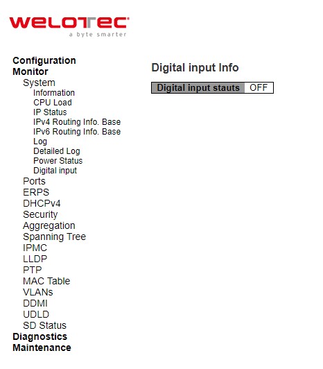
Digital Input
Status of Digital Input (DI) can be checked on this webpage shown in Figure 3.10. When it is “ON”, the device detects the signal from DI port. When it is “OFF”, the device will not detect the signal from DI port.
Ports
State
This State webpage shown in Figure 3.11 provides an overview of the current switch port states. The port states are typically illustrated as follows:
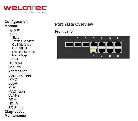
Check the Auto-refresh box to refresh the page automatically. Automatic refresh occurs every 3 seconds. Click Refresh button to refresh the page immediately.
Traffic Overview
This Traffic Overview webpage provides an overview of general traffic statistics for all ports of managed switch as shown in Figure 3.12. Table 3.7 describes column labels for the Port Statics Overview.
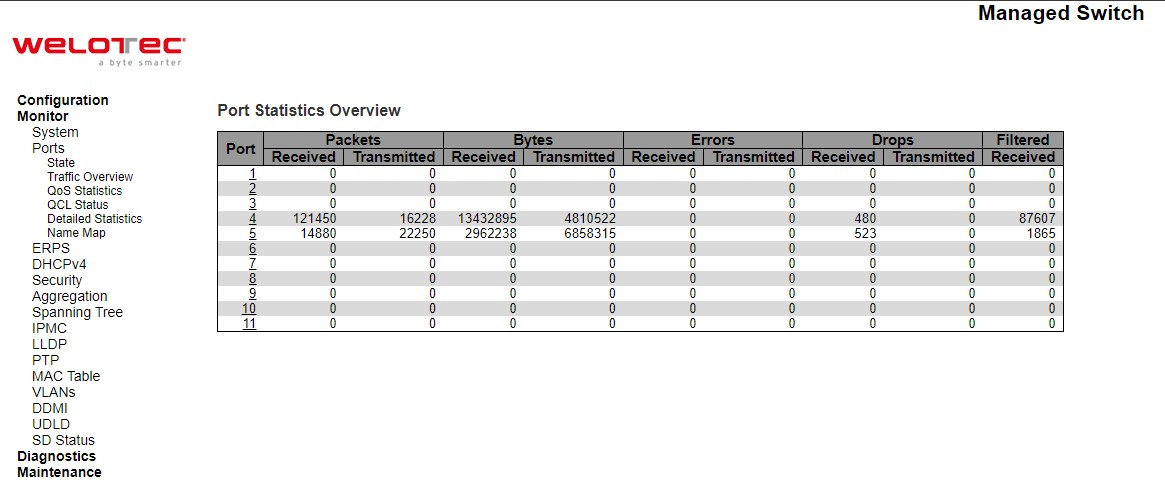
Table 3.7 Monitoring Descriptions of Traffic Overview of Ports:
Label |
Description |
Factory Default |
|---|---|---|
Port |
The logical port for the settings contained in the same row. |
Port Number |
Packets |
The number of received and transmitted packets per port. |
0 |
Bytes |
The number of received and transmitted bytes per port. |
0 |
Errors |
The number of frames received in error and the number of incomplete transmissions per port. |
0 |
Drops |
The number of frames discarded due to ingress or egress congestion. |
0 |
Filtered |
The number of received frames filtered by the forwarding process |
0 |
Check the Auto-refresh box to refresh the page automatically. Automatic refresh occurs every 3 seconds. Click Refresh button to refresh the page immediately.
QoS Statistics
QoS Statistics webpage in Figure 3.13 provides statistics for different queues on all managed switch’s ports. The labels of the Queueing Counters are described in Table 3.8.
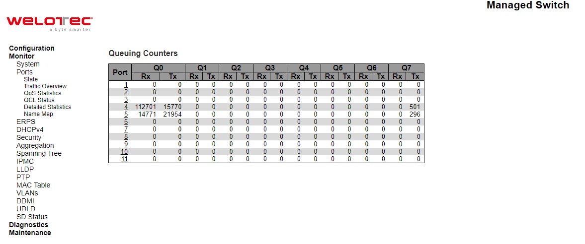
Table 3.8 Monitoring Descriptions of Queuing Counters:
Label |
Description |
|---|---|
Port |
The logical port for the settings contained in the same row. |
Qn |
There are 8 QoS queues per port. Q0 is the lowest priority queue |
Rx/Tx |
The number of received and transmitted packets per queue |
Check the Auto-refresh box to refresh the page automatically. Automatic refresh occurs every 3 seconds. Click Clear button to clears the counters for all ports. Click Refresh button to refresh the page immediately.
QCL Status
This webpage in Figure 3.14 shows the QoS Control List (QCL) status by different QCL users. Each row describes the QoS Control Entry (QCE) that is defined. It is a conflict if a specific QCE is not applied to the hardware due to hardware limitations. The maximum number of QCEs is 256 on each switch. Table 3.9 summarizes the descriptions of the labels in the QoS Control List Status.
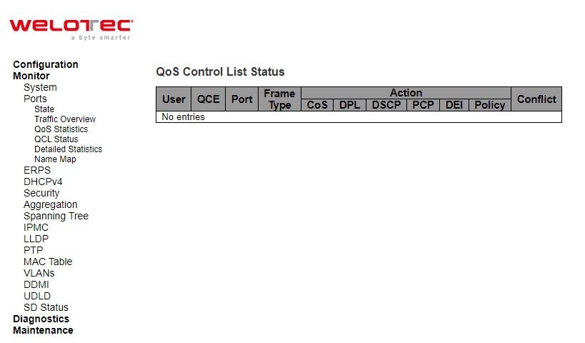
Table 3.9 Monitoring Descriptions of QoS Control List Status:
Label |
Description |
|---|---|
User |
Indicates the QCL user |
QCE |
Indicates the QCE id. |
Port |
Indicates the list of ports configured with the QCE. |
Frame Type |
Indicates the type of frame. Possible values are: |
Action |
Indicates the classification action taken on ingress frame if parameters configured are matched with the frame’s content. Possible actions are: |
Conflict |
Displays Conflict status of QCL entries. As H/W resources are shared by multiple applications. It may happen that resources required to add a QCE may not be available, in that case it shows conflict status as ‘Yes’, otherwise it is always ‘No’. Please note that conflict can be resolved by releasing the H/W resources required to add QCL entry on pressing ‘Resolve Conflict’ button |
Select the QCL status from this Combined drop-down list. Check the Auto-refresh box to refresh the page automatically.
Automatic refresh occurs every 3 seconds. Click Resolve Conflict button to release the resources required to add QCL entry, in case the conflict status for any QCL entry is ‘yes’. Click Clear button to clear the counters for all ports. Click Refresh button to refresh the page immediately
Detailed Statistics
This webpage in Figure 3.15 provides detailed traffic statistics for a specific switch port. The user can use the port select box to select which switch port details to display. The displayed counters are the totals for receive and transmit, the size counters for receive and transmit, and the error counters for receive and transmit. Descriptions of statistics labels are summarized in Table 3.10.
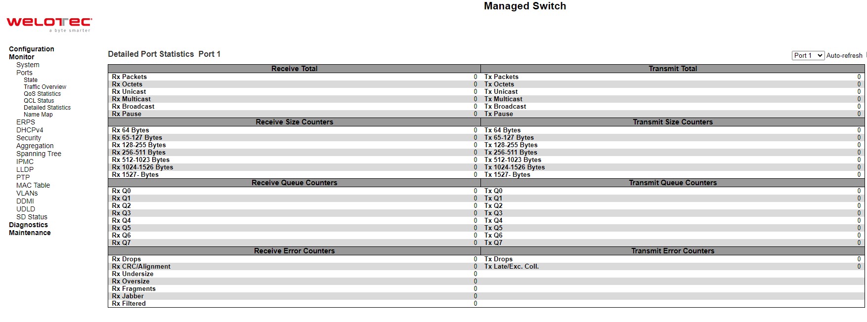
Table 3.10 Monitoring Descriptions of Detailed Port Statistics:
Label |
Description |
|---|---|
Receive Total and Transmit Total |
|
Rx and Tx Packets |
The number of received and transmitted (good and bad) packets. |
Rx and Tx Octets |
The number of received and transmitted (good and bad) bytes. Includes FCS, but excludes framing bits. |
Rx and Tx Unicast |
The number of received and transmitted (good and bad) unicast packets. |
Rx and Tx Multicast |
The number of received and transmitted (good and bad) multicast packets. |
Rx and Tx Broadcast |
The number of received and transmitted (good and bad) broadcast packets. |
Rx and Tx Pause |
A count of the MAC Control frames received or transmitted on this port that have an opcode indicating a PAUSE operation. |
Receive and Transmit Size Counters |
The number of received and transmitted (good and bad) multicast packets. |
Receive and Transmit Queue Counters |
The number of received and transmitted (good and bad) broadcast packets. |
Receive Error Counters |
|
Rx Drops |
The number of frames dropped due to lack of receive buffers or egress congestion. |
Rx CRC/Alignment |
The number of frames received with CRC or alignment errors. |
Rx Undersize |
The number of short frames received with valid CRC. Short frames are frames that are smaller than 64 bytes. |
Rx Oversize |
The number of long frames received with valid CRC. Long frames are frames that are longer than the configured maximum frame length for this port. |
Rx Fragments |
The number of short frames received with invalid CRC. Short frames are frames that are smaller than 64 bytes. |
Rx Jabber |
The number of long frames received with invalid CRC. Long frames are frames that are longer than the configured maximum frame length for this port. |
Rx Filtered |
The number of received frames filtered by the forwarding process |
Tx Drops |
The number of frames dropped due to output buffer congestion |
Tx Late/Exc. Coll |
The number of frames dropped due to excessive or late collisions |
The port select box determines which port is affected by clicking the buttons.
Check the Auto-refresh box to refresh the page automatically. Automatic refresh occurs every 3 seconds. Click Clear button to clear the counters for all ports. Click Refresh button to refresh the page immediately
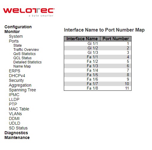
Name Map
This webpage provides interface name to port number mapping. Many Web pages use a port number to express an interface, whereas Command Line Interface (CLI) uses interface names. The table shown in Figure 3.16 provides a means to convert from one to the other.
ERPS
ERPS is an abbreviation for Ethernet Ring Protection Switching defined in ITU/T G.8032. It provides fast protection and recovery switching for Ethernet traffic in a ring topology while also ensuring that the Ethernet layer remains loop-free. This ERPS webpage reports the current status of ERPS instances on the managed switch as shown in Figure 3.17.
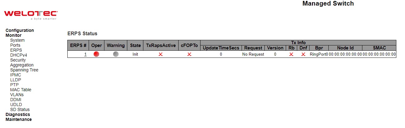
Table 3.11 Description of ERPS Status:
Label |
Description |
|---|---|
ERPS |
The ID of the ERPS. Click on link to get to ERPS instance page, you can reset counters and issue commands. |
Oper |
The operational state of ERPS instance. |
Warning |
Operational warnings of ERPS instance. |
State |
Specifies protection/node state of ERPS. |
TxRapsActive |
Specifies whether we are currently supposed to be transmitting R-APS PDUs on our ring ports. |
cFOPTo |
Failure of Protocol - R-APS Rx Time Out. |
Tx Info |
|
UpdateTimeSecs |
Time in seconds since boot that this structure was last updated. |
Request |
Request/state according to G.8032, table 10-3. |
Version |
Version of received/used R-APS Protocol. 0 means v1, 1 means v2, etc. |
Rb |
RB (RPL blocked) bit of R-APS info. See Figure 10-3 of G.8032. |
Dnf |
DNF (Do Not Flush) bit of R-APS info. See Figure 10-3 of G.8032.” |
Bpr |
BPR (Blocked Port Reference) of R-APS info. See Figure 10-3 of G.8032 |
Node Id |
Node ID of this request |
SMAC |
The Source MAC address used in the request/state |
Figure 3.18 shows detailed status of the EPRS where the parameters and commands are described in Table 3.12
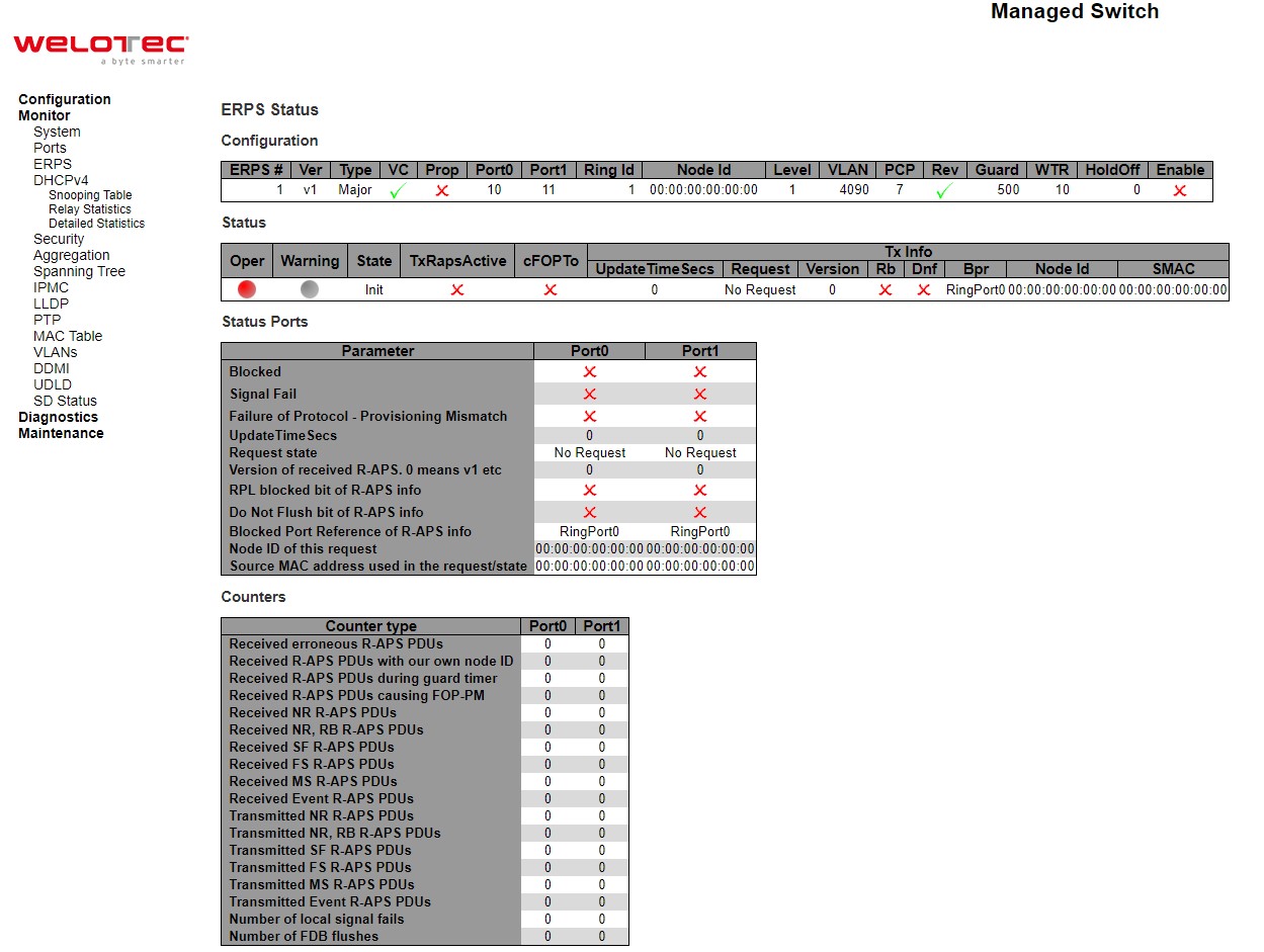
Table 3.12 Description of ERPS Detailed Status:
Label |
Description |
|---|---|
Configuration |
This table shows the current configuration for this ERPS instance. Go to the ERPS Configuration help page for further explanation. |
Status |
This shows the current status of the ERPS instance. Go to the ERPS Status help page for further explanation. |
Status Ports |
This shows the current status of the ERPS instance. Go to the ERPS Status help page for further explanation. |
Counters |
This shows a number of counters useful for debug purpose. The Counter type column indicate the counted frame attribute. |
ERPS Command |
No request: There is no active local command on this instance. Issuing this command has no effect. |
DHCPv4
Snooping Table
This Snooping Table webpage shown in Figure 3.19 displays the dynamic IP assigned information after DHCP Snooping mode is disabled. All DHCP clients obtained the dynamic IP address from the DHCP server will be listed in this table except for local VLAN interface IP addresses. Entries in the Dynamic DHCP snooping Table are shown on this page.
Each page shows up to 99 entries from the Dynamic DHCP snooping table, default being 20, selected through the “entries per page” input field. When first visited, the web page will show the first 20 entries from the beginning of the Dynamic DHCP snooping Table. The “MAC address” and “VLAN” input fields allow the user to select the starting point in the Dynamic DHCP snooping Table. Clicking the Refresh button will update the displayed table starting from that or the closest next Dynamic DHCP snooping Table match. In addition, the two input fields will - upon a Refresh button click - assume the value of the first displayed entry, allowing for continuous refresh with the same start address. The >> will use the last entry of the currently displayed table as a basis for the next lookup. When the end is reached the text “No more entries” is shown in the displayed table. Use the |<< button to start over.
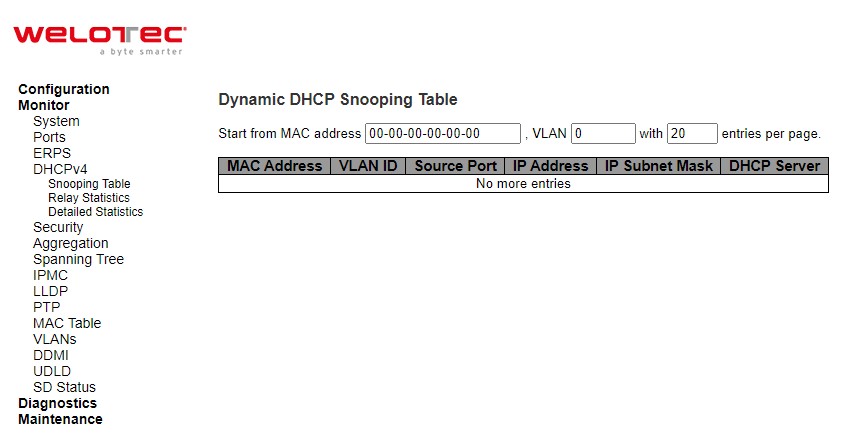
Table 3.13 Monitoring Descriptions of Dynamic DHCP Snooping Table:
Label |
Description |
|---|---|
MAC Address |
User MAC address of the entry. |
VLAN ID |
VLAN-ID in which the DHCP traffic is permitted. |
Source Port |
Switch Port Number for which the entries are displayed. |
IP Address |
User IP address of the entry. |
IP Subnet Mask |
User IP subnet mask of the entry |
DHCP Server |
DHCP Server address of the entry |
Check Auto-refresh box to refresh the page automatically. Automatic refresh occurs every 3 seconds. Click Clear button to clear DHCP Message Received Counters and DHCP Message Sent Counters. Click Refresh button to refresh the page immediately. Click |<< to update the table starting from the first entry in the Dynamic DHCP snooping Table. Click >> to update the table entries, starting from the last entry currently displayed.
Relay Statistics
This webpage provides statistics for DHCP relay as shown in Figure 3.20. Description of each Server Statistics is summarized in Table 3.14.
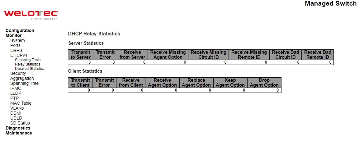
Table 3.14 Monitoring Descriptions of DHCP Relay Statistics:
Label |
Description |
|---|---|
Server Statistics |
|
Transmit To Server |
The number of packets that are relayed from client to server. |
Transmit Error |
The number of packets that resulted in errors while being sent to clients. |
Receive from Server |
The number of packets received from server. |
Receive Missing Agent Option |
The number of packets received without agent information options. |
Receive Missing Circuit ID |
The number of packets received with the Circuit ID option missing. |
Receive Missing Remote ID |
The number of packets received with the Remote ID option missing. |
Receive Bad Circuit ID |
The number of packets whose Circuit ID option did not match known circuit ID. |
Receive Bad Remote ID |
The number of packets whose Remote ID option did not match known Remote ID. |
Client Statistics |
|
Transmit To Client |
The number of relayed packets from server to client. |
Transmit Error |
The number of packets that resulted in error while being sent to servers. |
Receive from Client |
The number of received packets from server. |
Receive Agent Option |
The number of received packets with relay agent information option. |
Replace Agent Option |
The number of packets which were replaced with relay agent information option. |
Keep Agent Option |
The number of packets whose relay agent information was retained. |
Drop Agent Option |
The number of packets that were dropped which were received with relay agent information |
Check Auto-refresh box to refresh the page automatically. Automatic refresh occurs every 3 seconds. Click Refresh button to refresh the page immediately. Click Clear button clear all statistics.
Detailed Statistics
This Detailed Statistics webpage in Figure 3.21 provides statistics for DHCP snooping. Notice that the normal forward perport TX statistics is not increased if the incoming DHCP packet is done by L3 forwarding mechanism. And clear the statistics on specific port may not take effect on global statistics since it gathers the different layer overview. Descriptions of Statistics are summarized in Table 3.15.
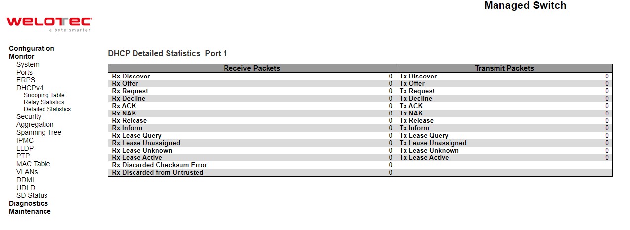
Table 3.15 Monitoring Descriptions of DHCP Detailed Statistics Port 1:
Label |
Description |
|---|---|
Rx and Tx Discover |
The number of discover (option 53 with value 1) packets received and transmitted. |
Rx and Tx Offer |
The number of offer (option 53 with value 2) packets received and transmitted. |
Rx and Tx Request |
The number of request (option 53 with value 3) packets received and transmitted. |
Rx and Tx Decline |
The number of decline (option 53 with value 4) packets received and transmitted. |
Rx and Tx ACK |
The number of ACK (option 53 with value 5) packets received and transmitted. |
Rx and Tx NAK |
The number of NAK (option 53 with value 6) packets received and transmitted. |
Rx and Tx Release |
The number of release (option 53 with value 7) packets received and transmitted |
Rx and Tx Inform |
The number of inform (option 53 with value 8) packets received and transmitted. |
Rx and Tx Lease Query |
The number of lease query (option 53 with value 10) packets received and transmitted. |
Rx and Tx Lease Unassigned |
The number of lease unassigned (option 53 with value 11) packets received and transmitted. |
Rx and Tx Lease Unknown |
The number of lease unknown (option 53 with value 12) packets received and transmitted. |
Rx and Tx Lease Active |
The number of lease active (option 53 with value 13) packets received and transmitted. |
Rx Discarded Checksum Error |
The number of discard packet that IP/UDP checksum is error. |
Rx Discarded from Untrusted |
The number of discarded packets that are coming from untrusted port |
The  DHCP user select box determines which user is affected by clicking the buttons.
  The port select box determines which port is affected by clicking the buttons. Auto-refresh
  : Check this box to refresh the page automatically. Automatic refresh occurs every 3 seconds. Click Refresh button to refresh the page immediately. Click Clear button to blear all statistics.
Security
Network
Port Security Overview
This webpage in Figure 3.22 shows the Port Security status. Port Security is a module with no direct configuration. Configuration comes indirectly from other modules - the user modules. When a user module has enabled port security on a port, the port is set-up for software-based learning. In this mode, frames from unknown MAC addresses are passed on to the port security module, which in turn asks all user modules whether to allow this new MAC address to forward or block it. For a MAC address to be set in the forwarding state, all enabled user modules must unanimously agree on allowing the MAC address to forward. If only one chooses to block it, it will be blocked until that user module decides otherwise. The status page is divided into two sections - one with a legend of user modules and one with the actual port status. Table 3.16 summarizes the descriptions of Port Security Switch Status.
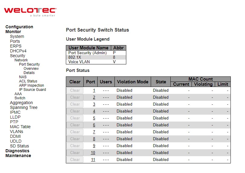
Table 3.16 Monitoring Descriptions of Port Security Switch Status:
Label |
Description |
|---|---|
User Module Legend |
|
User Module Name |
The full name of a module that may request Port Security services. |
Abbr |
A one-letter abbreviation of the user module. This is used in the Users column in the port status table. |
Port Status |
|
Clear |
Click to remove all dynamic MAC addresses on all VLANs on this port. The button is only clickable if number of secured MAC addresses is non-zero. |
Port |
The port number for which the status applies. Click the port number to see the status for this particular port. |
Users |
Each of the user modules has a column that shows whether that module has enabled Port Security or not. A ‘-’ means that the corresponding user module is not enabled, whereas a letter indicates that the user module abbreviated by that letter (see Abbr) has enabled port security. |
Violation Mode |
Shows the configured Violation Mode of the port. It can take one of four values: |
State |
Shows the current state of the port. It can take one of four values: |
MAC Count (Current, Violating, Limit) |
The three columns indicate the number of currently learned MAC addresses (forwarding as well as blocked), the number of violating MAC address (only counting in Restrict mode) and the maximum number of MAC addresses that can be learned on the port, respectively. |
Check Auto-refresh box to refresh the page automatically. Automatic refresh occurs every 3 seconds. Click Refresh button to refresh the page immediately.
Port Security Details
This page shows the MAC addresses secured by the Port Security module. Port Security is a module with no direct configuration. Configuration comes indirectly from other modules - the user modules. When a user module has enabled port security on a port, the port is set-up for software-based learning. In this mode, frames from unknown MAC addresses are passed on to the port security module, which in turn asks all user modules whether to allow this new MAC address to forward or block it. For a MAC address to be set in the forwarding state, all enabled user modules must unanimously agree on allowing the MAC address to forward. If only one chooses to block it, it will be blocked until that user module decides otherwise.
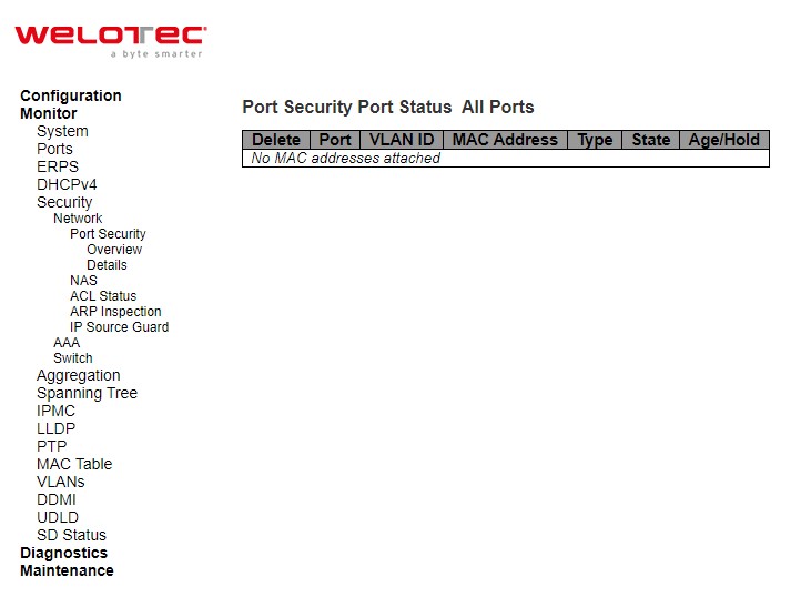
Table 3.17 Monitoring Descriptions of Port Security Port Status All Ports:
Label |
Description |
|---|---|
Delete |
Click to remove this particular MAC addresses from MAC address table. The button is only clickable if the entry type is Dynamic. Use the “Configuration→Security→Port Security→MAC Addresses” page to remove Static and Sticky entries. |
Port |
If all ports are shown (can be selected through the drop-down box on the top right), this one shows the port to which the MAC address is bound. |
MAC Address & VLAN ID |
The MAC address and VLAN ID that is seen on this port. If no MAC addresses are learned, a single row stating “No MAC addresses attached” is displayed. |
Type |
Indicates the type of entry. Takes one of three values:
|
State |
Indicates whether the corresponding MAC address is blocked or forwarding. In the blocked state, it will not be allowed to transmit or receive traffic. |
Age/Hold |
If at least one user module has decided to block this MAC address, it will stay in the blocked state until the hold time (measured in seconds) expires. If all user modules have decided to allow this MAC address to forward, and aging is enabled, the Port Security module will periodically check that this MAC address still forwards traffic. If the age period (measured in seconds) expires and no frames have been seen, the MAC address will be removed from the MAC table. Otherwise, a new age period will begin. If aging is disabled or a user module has decided to hold the MAC address indefinitely, a dash (-) will be shown |
Use the port select box to select which port to show status for. Click on Auto-refresh box to refresh the page automatically. Automatic refresh occurs every 3 seconds. Click Refresh button to refresh the page immediately
NAS Switch
This page provides an overview of the current NAS port states. NAS is an acronym for Network Access Server. The NAS is meant to act as a gateway to guard access to a protected source. A client connects to the NAS, and the NAS connects to another resource asking whether the client’s supplied credentials are valid. Based on the answer, the NAS then allows or disallows access to the protected resource. An example of a NAS implementation is IEEE 802.1X.
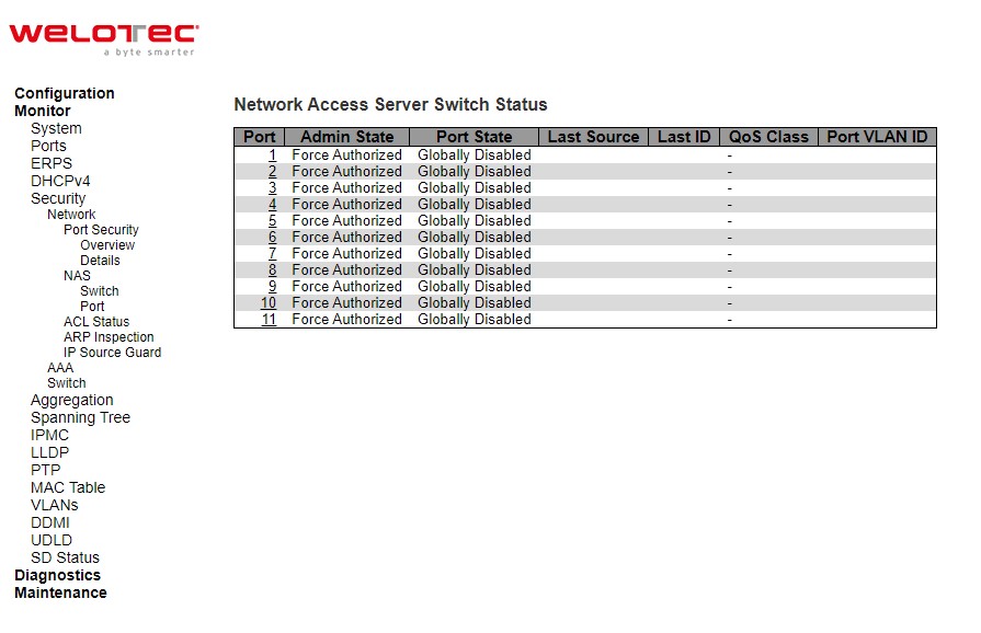
Table 3.18 Monitoring Descriptions of Network Access Server Switch Status:
Label |
Description |
|---|---|
Port |
The switch port number. Click to navigate to detailed NAS statistics for this port. |
Admin State |
The port’s current administrative state. Refer to NAS Admin State for a description of possible values. |
Port State |
The current state of the port. Refer to NAS Port State for a description of the individual states. |
Last Source |
The source MAC address carried in the most recently received EAPOL frame for EAPOL-based authentication, and the most recently received frame from a new client for MAC-based authentication. |
Last ID |
The user name (supplicant identity) carried in the most recently received Response Identity EAPOL frame for EAPOL-based authentication, and the source MAC address from the most recently received frame from a new client for MAC-based authentication. |
QoS Class |
QoS Class assigned to the port by the RADIUS server if enabled. |
Port VLAN ID |
The VLAN ID that NAS has put the port in. The field is blank, if the Port VLAN ID is not overridden by NAS. If the VLAN ID is assigned by the RADIUS server, “(RADIUS-assigned)” is appended to the VLAN ID. Read more about RADIUS-assigned VLANs at Configuration⭢Security⭢Network⭢NAS. If the port is moved to the Guest VLAN, “(Guest)” is appended to the VLAN ID. Read more about Guest VLANs Configuration⭢Security⭢Network>NAS |
Check Auto-refresh box to refresh the page automatically. Automatic refresh occurs every 3 seconds. Click Refresh button to refresh the page immediately.
NAS Port
This page provides detailed NAS statistics for a specific switch port running EAPOL-based IEEE 802.1X authentication. For MAC-based ports, it shows selected backend server (RADIUS Authentication Server) statistics, only. Use the port select box to select which port details to be displayed.
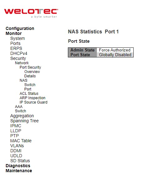
Table 3.19 Monitoring Descriptions of NAS Statistics Port 1:
Label |
Description |
|---|---|
Port State |
|
Admin State |
The port’s current administrative state. Refer to NAS Admin State for a description of possible values. |
Port State |
The current state of the port. Refer to NAS Port State for a description of the individual states. |
QoS Class |
The QoS class assigned by the RADIUS server. The field is blank if no QoS class is assigned. |
Port VLAN ID |
The VLAN ID that NAS has put the port in. The field is blank, if the Port VLAN ID is not overridden by NAS. If the VLAN ID is assigned by the RADIUS server, “(RADIUS-assigned)” is appended to the VLAN ID. Read more about RADIUS-assigned VLANs Configuration⭢Security⭢Network⭢NAS. If the port is moved to the Guest VLAN, “(Guest)” is appended to the VLAN ID. Read more about Guest VLANs Configuration⭢Security>Network⭢NAS. |
Port Counters |
|
EAPOL Counters |
These supplicant frame counters are available for the following administrative states: • Force Authorized • Force Unauthorized • Port-based 802.1X |
Backend Server Counters |
These backend (RADIUS) frame counters are available for the following administrative states: • Port-based 802.1X |
Last Supplicant/Client Info |
Information about the last supplicant/client that attempted to authenticate. This information is available for the following administrative states: • Port-based 802.1X • Single 802.1X • Multi 802.1X • MAC-based Auth. |
Selected Counters |
|
Selected Counters |
The Selected Counters table is visible when the port is in one of the following administrative states: • MAC-based Auth. The table is identical to and is placed next to the Port Counters table, and will be empty if no MAC address is currently selected. To populate the table, select one of the attached MAC Addresses from the table below. |
Attached MAC Addresses |
|
Identity |
Shows the identity of the supplicant, as received in the Response Identity EAPOL frame. Clicking the link causes the supplicant’s EAPOL and Backend Server counters to be shown in the Selected Counters table. If no supplicants are attached, it shows No supplicants attached. This column is not available for MAC-based Auth. |
MAC Address |
For MAC-based Auth., this column holds the MAC address of the attached client. Clicking the link causes the client’s Backend Server counters to be shown in the Selected Counters table. If no clients are attached, it shows No clients attached. |
VLAN ID |
This column holds the VLAN ID that the corresponding client is currently secured through the Port Security module. |
State |
The client can either be authenticated or unauthenticated. In the authenticated state, it is allowed to forward frames on the port, and in the unauthenticated state, it is blocked. As long as the backend server hasn’t successfully authenticated the client, it is unauthenticated. If an authentication fails for one or the other reason, the client will remain in the unauthenticated state for Hold Time seconds. |
Last Authentication |
Shows the date and time of the last authentication of the client (successful as well as unsuccessful) |
The port select box determines which port is affected when clicking the buttons. Check Auto-refresh box to refresh the page automatically. Automatic refresh occurs every 3 seconds. Click Refresh button to refresh the page immediately. The Clear button is available in the following modes: Force Authorized, Force Unauthorized, Port-based 802.1X, and Single 802.1X mode. Click to clear the counters for the selected port. The Clear All button is available in the following modes: Multi 802.1X and MAC-based Auth.X. Click to clear both the port counters and all of the attached client’s counters. The “Last Client” will not be cleared. However, the Clear This button is available in the following modes: Multi 802.1X and MACbased Auth.X. Click to clear only the currently selected client’s counters.
ACL Status
This page shows the ACL status by different ACL users. Each row describes the ACE that is defined. It is a conflict if a specific ACE is not applied to the hardware due to hardware limitations. The maximum number of ACEs is 512 on each switch.
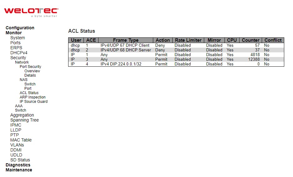
Table 3.20 Monitoring Descriptions of ACL Status:
Label |
Description |
|---|---|
User |
Indicates the ACL user. |
ACE |
Indicates the ACE ID on local switch. |
Frame Type |
Indicates the frame type of the ACE. Possible values are: |
Action |
Indicates the forwarding action of the ACE. |
Rate Limiter |
Indicates the rate limiter number of the ACE. The allowed range is 1 to 16. When Disabled is displayed, the rate limiter operation is disabled. |
CPU |
Forward packet that matched the specific ACE to CPU. |
Counter |
The counter indicates the number of times the ACE was hit by a frame. |
Conflict |
Indicates the hardware status of the specific ACE. The specific ACE is not applied to the hardware due to hardware limitations |
The select box ![][224] determines which ACL user is affected by clicking the buttons. Check Auto-refresh box to refresh the page automatically. Automatic refresh occurs every 3 seconds. Click Refresh button to refresh the page immediately
ARP Inspection
Entries in the Dynamic ARP Inspection Table are shown on this page. The Dynamic ARP Inspection Table contains up to 256 entries, and is sorted first by port, then by VLAN ID, then by MAC address, and then by IP address. All dynamic entries are learning from DHCP Snooping.
Each page shows up to 99 entries from the Dynamic ARP Inspection table, default being 20, selected through the “entries per page” input field. When first visited, the web page will show the first 20 entries from the beginning of the Dynamic ARP Inspection Table. The “Start from port address”, “VLAN”, “MAC address” and “IP address” input fields allow the user to select the starting point in the Dynamic ARP Inspection Table. Clicking the Refresh button will update the displayed table starting from that or the closest next Dynamic ARP Inspection Table match. In addition, the two input fields will - upon a Refresh button click - assume the value of the first displayed entry, allowing for continuous refresh with the same start address. The >> will use the last entry of the currently displayed table as a basis for the next lookup. When the end is reached the text “No more entries” is shown in the displayed table. Use the |<< button to start over.
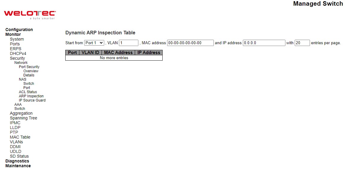
Table 3.21 Monitoring Descriptions of Dynamic ARP Inspection Table:
Label |
Description |
|---|---|
Port |
Switch Port Number for which the entries are displayed. |
VLAN ID |
VLAN-ID in which the ARP traffic is permitted. |
MAC Address |
User MAC address of the entry. |
IP Address |
User IP address of the entry |
Check Auto-refresh box to refresh the page automatically. Automatic refresh occurs every 3 seconds. Click Refresh button to refresh the page immediately. Click Clear button to flushes all dynamic entries. Click |<< to update the table starting from the first entry in the Dynamic ARP Inspection Table. Click >> to update the table, starting with the entry after the last entry currently displayed.
IP Source Guard
Entries in the Dynamic IP Source Guard Table are shown on this page. The Dynamic IP Source Guard Table is sorted first by port, then by VLAN ID, then by IP address, and then by MAC address.
Each page shows up to 99 entries from the Dynamic IP Source Guard table, default being 20, selected through the “entries per page” input field. When first visited, the web page will show the first 20 entries from the beginning of the Dynamic IP Source Guard Table. The “Start from port address”, “VLAN” and “IP address” input fields allow the user to select the starting point in the Dynamic IP Source Guard Table. Clicking the Refresh button will update the displayed table starting from that or the closest next Dynamic IP Source Guard Table match. In addition, the two input fields will - upon a Refresh button click - assume the value of the first displayed entry, allowing for continuous refresh with the same start address. The >> will use the last entry of the currently displayed table as a basis for the next lookup. When the end is reached the text “No more entries” is shown in the displayed table. Use the |<< button to start over.
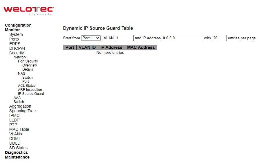
Table 3.22 Monitoring Descriptions of Dynamic IP Source Guard Table:
Label |
Description |
|---|---|
Port |
Switch Port Number for which the entries are displayed. |
VLAN ID |
VLAN-ID in which the IP traffic is permitted. |
IP Address |
User IP address of the entry |
MAC Address |
Source MAC address |
Check Auto-refresh box to refresh the page automatically. Automatic refresh occurs every 3 seconds. Click Refresh button to refresh the page immediately. Click Clear button to flush all dynamic entries. Click |<< to update the table starting from the first entry in the Dynamic ARP Inspection Table. Click >> to update the table, starting with the entry after the last entry currently displayed.
AAA
RADIUS Overview
This page provides an overview of the status of the RADIUS servers configurable on the Authentication configuration page.
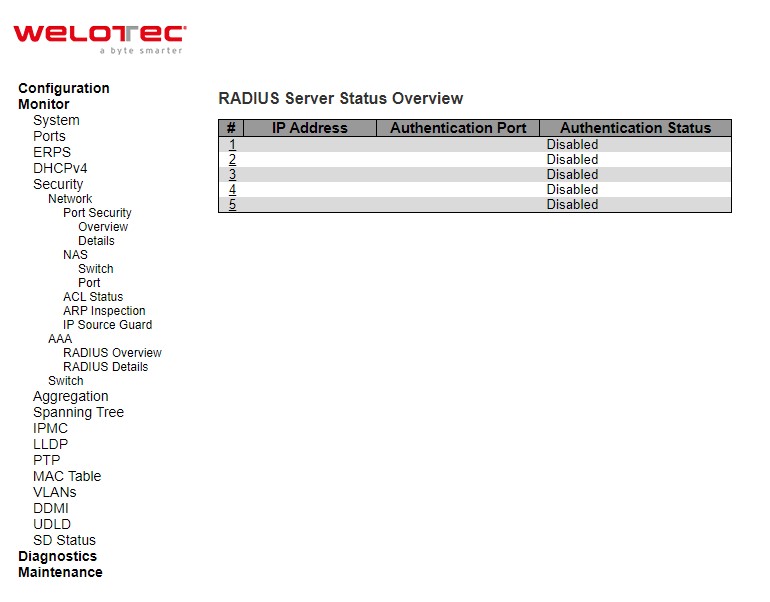
Table 3.23 Monitoring Descriptions of RADIUS Server Status Overview:
Label |
Description |
|---|---|
# |
The RADIUS server number. Click to navigate to detailed statistics for this server. |
IP Address |
The IP address of this server |
Authentication Port |
UDP port number for authentication |
Authentication Status |
The current status of the server. This field takes one of the following values: |
Accounting Port |
UDP port number for accounting. |
Accounting Status |
The current status of the server. This field takes one of the following values: |
Check Auto-refresh box to refresh the page automatically. Automatic refresh occurs every 3 seconds. Click Refresh button to refresh the page immediately
After clicking on each port, the following webpage will be launched, as shown in Figure 3.30. Table 3.24 shows the description of each port’s RADIUS server status.
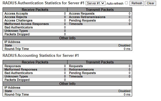
Table 3.24 Monitoring Descriptions of Each Port’s RADIUS Server Status:
Label |
Description |
|---|---|
RADIUS Authentication Statistics for Server#1 |
RADIUS Authentication Statistics map closely to those specified in RFC4668 - RADIUS Authentication Client MIB. Use the server select box to switch between the backend servers to show details for. For RADIUS authentication server packet counter, there are seven receive and four transmit counters. |
Receive Packets |
|
Access Accepts |
The number of RADIUS Access-Accept packets (valid or invalid) received from the server. |
Access Rejects |
The number of RADIUS Access-Reject packets (valid or invalid) received from the server. |
Access Challenges |
The number of RADIUS Access-Challenge packets (valid or invalid) received from the server. |
Malformed Access Responses |
The number of malformed RADIUS Access-Response packets received from the server. Malformed packets include packets with an invalid length. Bad authenticators or Message Authenticator attributes or unknown types are not included as malformed access responses. |
Bad Authenticators |
The number of RADIUS Access-Response packets containing invalid authenticators or Message Authenticator attributes received from the server. |
Unknown Types |
The number of RADIUS packets that were received with unknown types from the server on the authentication port and dropped. |
Packets Dropped |
The number of RADIUS packets that were received from the server on the authentication port and dropped for some other reason. |
Transmit Packets |
|
Access Requests |
The number of RADIUS Access-Request packets sent to the server. This does not include retransmissions. |
Access Retransmission |
The number of RADIUS Access-Request packets retransmitted to the RADIUS authentication server. |
Pending Requests |
The number of RADIUS Access-Request packets destined for the server that have not yet timed out or received a response. This variable is incremented when an Access-Request is sent and decremented due to receipt of an Access-Accept, Access-Reject, Access-Challenge, timeout, or retransmission. |
Timeouts |
The number of authentication timeouts to the server. After a timeout, the client may retry to the same server, send to a different server, or give up. A retry to the same server is counted as a retransmit as well as a timeout. A send to a different server is counted as a Request as well as a timeout. |
Other Info |
|
IP Address |
IP address and UDP port for the authentication server in question. |
State |
Shows the state of the server. It takes one of the following values: |
Round-Trip Time |
The time interval (measured in milliseconds) between the most recent Access-Reply/Access-Challenge and the Access-Request that matched it from the RADIUS authentication server. The granularity of this measurement is 100 ms. A value of 0 ms indicates that there hasn’t been round-trip communication with the server yet |
RADIUS Details
This page provides detailed statistics for a particular RADIUS server.
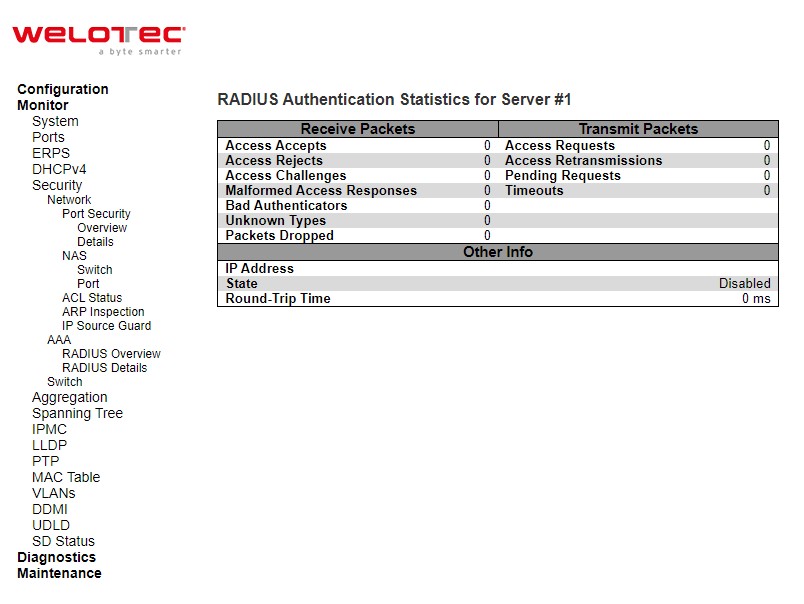
Table 3.25 Monitoring Descriptions of RADIUS Authentication and Accounting Statistics:
Label |
Description |
|---|---|
RADIUS Authentication Statistics for Server#1 |
RADIUS Authentication Statistics map closely to those specified in RFC4668 – RADIUS Authentication Client MIB. Use the server select box to switch between the backend servers to show details for. For RADIUS authentication server packet counter, there are seven receive and four transmit counters. |
Receive Packets |
|
Access Accepts |
The number of RADIUS Access-Accept packets (valid or invalid) received from the server. |
Access Rejects |
The number of RADIUS Access-Reject packets (valid or invalid) received from the server. |
Access Challenges |
The number of RADIUS Access-Challenge packets (valid or invalid) received from the server. |
Malformed Access Responses |
The number of malformed RADIUS Access Response packets received from the server. Malformed packets include packets with an invalid length. Bad authenticators or Message Authenticator attributes or unknown types are not included as malformed access responses. |
Bad Authenticators |
The number of RADIUS Access-Response packets containing invalid authenticators or Message Authenticator attributes received from the server. |
Unknown Types |
The number of RADIUS packets that were received with unknown types from the server on the authentication port and dropped. |
Packets Dropped |
The number of RADIUS packets that were received from the server on the authentication port and dropped for some other reason. |
Transmit Packets |
|
Access Requests |
The number of RADIUS Access-Request packets sent to the server. This does not include retransmissions. |
Access Retransmission |
The number of RADIUS Access-Request packets retransmitted to the RADIUS authentication server. |
Pending Requests |
The number of RADIUS Access-Request packets destined for the server that have not yet timed out or received a response. This variable is incremented when an Access-Request is sent and decremented due to receipt of an Access-Accept, Access-Reject, Access-Challenge, timeout, or retransmission. |
Timeouts |
The number of authentication timeouts to the server. After timeout a, the client may retry to the same server, send to a different server, or give up. A retry to the same server is counted as a retransmit as well as a timeout. A send to a different server is counted as a Request as well as a timeout. |
Other Info |
|
IP Address |
IP address and UDP port for the authentication server in question. |
State |
Shows the state of the server. It takes one of the following values: |
Round-Trip Time |
The time interval (measured in milliseconds) between the most recent Access-Reply/Access-Challenge and the Access-Request that matched it from the RADIUS authentication server. The granularity of this measurement is 100 ms. A value of 0 ms indicates that there hasn’t been round-trip communication with the server yet |
The server select box determines which server is affected by clicking the buttons. Click check Auto-refresh box to refresh the page automatically. Automatic refresh occurs every 3 seconds. Click Refresh button to refresh the page immediately. Click Clear button to clear the counters for the selected server. The “Pending Requests” counter will not be cleared by this operation.
Switch
RMON Statistics
This page provides an overview of RMON Statistics entries. Each page shows up to 99 entries from the Statistics table, default being 20, selected through the “entries per page” input field. When first visited, the web page will show the first 20 entries from the beginning of the Statistics table. The first displayed will be the one with the lowest ID found in the Statistics table.
The “Start from Control Index” allows the user to select the starting point in the Statistics table. Clicking the Refresh button will update the displayed table starting from that or the next closest Statistics table match.
The >> will use the last entry of the currently displayed entry as a basis for the next lookup. When the end is reached the text “No more entries” is shown in the displayed table. Use the |<< button to start over.
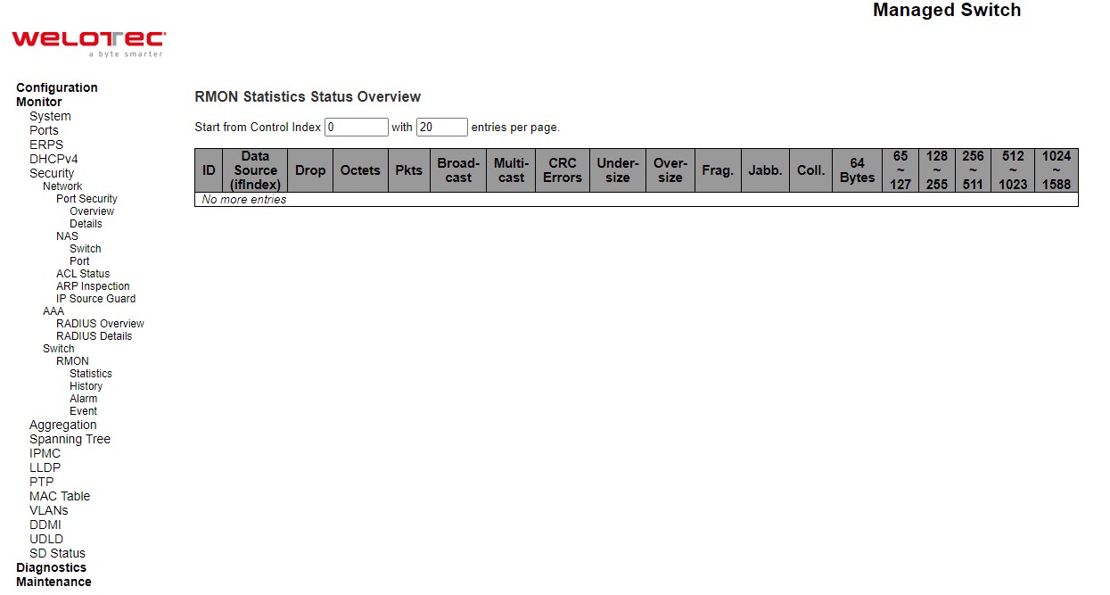
Table 3.26 Monitoring Descriptions of RMON Statistics Status Overview:
Label |
Description |
|---|---|
ID |
Indicates the index of Statistics entry. |
Data Source(ifIndex) |
The port ID which wants to be monitored. |
Drop |
The total number of events in which packets were dropped by the probe due to lack of resources. |
Octets |
The total number of octets of data (including those in bad packets) received on the network. |
Pkts |
The total number of packets (including bad packets, broadcast packets, and multicast packets) received. |
Broad-cast |
The total number of good packets received that were directed to the broadcast address. |
Multi-cast |
The total number of good packets received that were directed to a multicast address. |
CRC Errors |
The total number of packets received that had a length (excluding framing bits, but including FCS octets) of between 64 and 1518 octets, inclusive, but had either a bad Frame Check Sequence (FCS) with an integral number of octets (FCS Error) or a bad FCS with a non-integral number of octets (Alignment Error). |
Under-size |
The total number of packets received that were less than 64 octets. |
Over-size |
The total number of packets received that were longer than 1518 octets. |
Frag. |
The number of frames which size is less than 64 octets received with invalid CRC. |
Jabb. |
The number of frames which size is larger than 64 octets received with invalid CRC. |
Coll. |
The best estimate of the total number of collisions on this Ethernet segment. |
64 Bytes |
The total number of packets (including bad packets) received that were 64 octets in length. |
65~127 |
The total number of packets (including bad packets) received that were between 65 to 127 octets in length. |
128~255 |
The total number of packets (including bad packets) received that were between 128 to 255 octets in length. |
256~511 |
The total number of packets (including bad packets) received that were between 256 to 511 octets in length. |
512~1023 |
The total number of packets (including bad packets) received that were between 512 to 1023 octets in length |
1024~1588 |
The total number of packets (including bad packets) received that were between 1024 to 1588 octets in length |
Check Auto-refresh box to refresh the page automatically. Automatic refresh occurs every 3 seconds. Click Refresh button to refresh the page immediately. Click |<< to update the table starting from the first entry in the Statistics table, i.e. the entry with the lowest ID. Click >> to updates the table, starting with the entry after the last entry currently displayed.
RMON History
This page provides an overview of RMON History entries. Each page shows up to 99 entries from the History table, default being 20, selected through the “entries per page” input field. When first visited, the web page will show the first 20 entries from the beginning of the History table. The first displayed will be the one with the lowest History Index and Sample Index found in the History table. The “Start from History Index and Sample Index” allows the user to select the starting point in the History table. Clicking the Refresh button will update the displayed table starting from that or the next closest History table match. The >> will use the last entry of the currently displayed entry as a basis for the next lookup. When the end is reached the text “No more entries” is shown in the displayed table. Use the |<< button to start over.
Table 3.27 Monitoring Descriptions of RMON History Overview:
Label |
Description |
|---|---|
History Index |
Indicates the index of History control entry. |
Sample Index |
Indicates the index of the data entry associated with the control entry. |
Sample Start |
The value of sysUpTime at the start of the interval over which this sample was measured. |
Drop |
The total number of events in which packets were dropped by the probe due to lack of resources. |
Octets |
The total number of octets of data (including those in bad packets) received on the network. |
Pkts |
The total number of packets (including bad packets, broadcast packets, and multicast packets) received. |
Broadcast |
The total number of good packets received that were directed to the broadcast address. |
Multicast |
The total number of good packets received that were directed to a multicast address. |
CRCErrors |
The total number of packets received that had a length (excluding framing bits, but including FCS octets) of between 64 and 1518 octets, inclusive, but had either a bad Frame Check Sequence (FCS) with an integral number of octets (FCS Error) or a bad FCS with a non-integral number of octets (Alignment Error). |
Undersize |
The total number of packets received that were less than 64 octets. |
Oversize |
The total number of packets received that were longer than 1518 octets. |
Frag. |
The number of frames which size is less than 64 octets received with invalid CRC. |
Jabb. |
The number of frames which size is larger than 64 octets received with invalid CRC. |
Coll. |
The best estimate of the total number of collisions on this Ethernet segment. |
Utilization |
The best estimate of the mean physical layer network utilization on this interface during this sampling interval, in hundredths of a percent |
Click Auto-refresh box to refresh the page automatically. Automatic refresh occurs every 3 seconds. Click Refresh button to refresh the page immediately. Click |<< to update the table starting from the first entry in the Statistics table, i.e. the entry with the lowest ID. Click >> to updates the table, starting with the entry after the last entry currently displayed.
RMON Alarm
Configure RMON Alarm table on this page. The entry index key is ID.
Table 3.28 Monitoring Descriptions of RMON Alarm Overview:
Label |
Description |
|---|---|
Delete |
Check to delete the entry. It will be deleted during the next save. |
ID |
Indicates the index of the entry. The range is from 1 to 65535. |
Interval |
Indicates the interval in seconds for sampling and comparing the rising and falling threshold. The range is from 1 to 2^31-1. |
Variable |
Indicates the particular variable to be sampled, the possible variables are: InOctets: The total number of octets received on the interface, including framing characters. InUcastPkts: The number of unicast packets delivered to a higher-layer protocol. InNUcastPkts: The number of broad-cast and multicast packets delivered to a higher-layer protocol. InDiscards: The number of inbound packets that are discarded even the packets are normal. InErrors: The number of inbound packets that contained errors preventing them from being deliverable to a higher-layer protocol. InUnknownProtos: the number of the inbound packets that were discarded because of the unknown or un-support protocol. OutOctets: The number of octets transmitted out of the interface, including framing characters. OutUcastPkts: The number of uni-cast packets that request to transmit. OutNUcastPkts: The number of broad-cast and multi-cast packets that request to transmit. OutDiscards: The number of outbound packets that are discarded event the packets are normal. OutErrors: The number of outbound packets that could not be transmitted because of errors. OutQLen: The length of the output packet queue (in packets). |
Sample Type |
The method of sampling the selected variable and calculating the value to be compared against the thresholds, possible sample types are: Absolute: Get the sample directly. Delta: Calculate the difference between samples (default). |
Value |
The value of the statistic during the last sampling period. |
Startup Alarm |
The method of sampling the selected variable and calculating the value to be compared against the thresholds, possible sample types are: Rising Trigger alarm when the first value is larger than the rising threshold. Falling Trigger alarm when the first value is less than the falling threshold. RisingOrFalling Trigger alarm when the first value is larger than the rising threshold or less than the falling threshold (default). |
Rising Threshold |
Rising threshold value (-2147483648-2147483647). |
Rising Index |
Rising event index (1-65535). |
Falling Threshold |
Falling threshold value (-2147483648-2147483647) |
Falling Index |
Falling event index (1-65535) |
Click Add New Entry button to add a new access management entry. Click Save button to save changes. Click Reset button to undo any changes made locally and revert to previously saved values.
RMON Event
Configure RMON Event table on this page. The entry index key is ID.
Table 3.29 Monitoring Descriptions of RMON Event:
Label |
Description |
|---|---|
Event Index |
Indicates the index of the event entry. |
Log Index |
Indicates the index of the log entry. |
LogTime |
Indicates Event log time |
LogDescription |
Indicates the Event description |
Aggregation
Status
This page is used to see the status of ports in Aggregation group. Using multiple ports in parallel to increase the link speed beyond the limits of a port and to increase the redundancy for higher availability.
Table 3.30 Monitoring Descriptions of Aggregation Status:
Label |
Description |
|---|---|
Aggr ID |
The Aggregation ID associated with this aggregation instance. |
Name |
Name of the Aggregation group ID. |
Type |
Type of the Aggregation group (Static or LACP). |
Speed |
Speed of the Aggregation group. |
Configured ports |
Configured member ports of the Aggregation group |
Aggregated ports |
Aggregated member ports of the Aggregation group |
Check the Auto-refresh box to refresh the page automatically. Automatic refresh occurs every 3 seconds. Click Refresh button to refresh the page immediately.
LACP
System Status
This page provides a status overview for all LACP instances. LACP is an IEEE 802.3ad standard protocol. The Link Aggregation Control Protocol, allows bundling several physical ports together to form a single logical port.
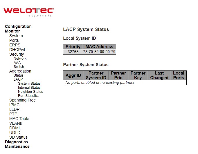
Table 3.31 Monitoring Descriptions of LACP System Status:
Label |
Description |
|---|---|
Aggr ID |
The Aggregation ID associated with this aggregation instance. For LLAG the id is shown as ‘isid:aggr-id’ and for GLAGs as ‘aggr-id’ |
Partner System ID |
The system ID (MAC address) of the aggregation partner. |
Partner Key |
The Key that the partner has assigned to this aggregation ID. |
Last changed |
The time since this aggregation changed. |
Local Ports |
Shows which ports are a part of this aggregation for this switch |
Check Auto-refresh box to refresh the page automatically. Automatic refresh occurs every 3 seconds. Click Refresh button to refresh the page immediately.
Internal Status
This page provides a status overview for the [LACP] internal (i.e. local system) status for all ports. Only ports that are part of an LACP group are shown. For details on the shown parameters please refer to IEEE 801.AX-2014.
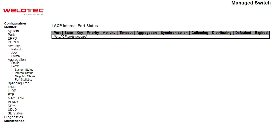
Table 3.32 Monitoring Descriptions of LACP Internal Port Status:
Label |
Description |
|---|---|
Port |
The switch port number. |
State |
The current port state:
|
Key |
The key assigned to this port. Only ports with the same key can aggregate together. |
Priority |
The priority assigned to this aggregation group. |
Activity |
The LACP mode of the group (Active or Passive). |
Timeout |
The timeout mode configured for the port (Fast or Slow). |
Aggregation |
Show whether the system considers this link to be “aggregable”; i.e., a potential candidate for aggregation. |
Synchronization |
Show whether the system considers this link to be “IN_SYNC”; i.e., it has been allocated to the correct LAG, the group has been associated with a compatible Aggregator, and the identity of the LAG is consistent with the System ID and operational Key information transmitted. |
Collecting |
Show if collection of incoming frames on this link is enabled. |
Distributing |
Show if distribution of outgoing frames on this link is enabled. |
Defaulted |
Show if the Actor’s Receive machine is using Defaulted operational Partner information. |
Expired |
Show if that the Actor’s Receive machine is in the EXPIRED state |
Check Auto-refresh box to refresh the page automatically. Automatic refresh occurs every 3 seconds. Click Refresh button to refresh the page immediately.
Neighbor Status
This page provides a status overview for the [LACP] neighbour status for all ports. Only ports that are part of an LACP group are shown. For details on the shown parameters please refer to IEEE 801.AX-2014.
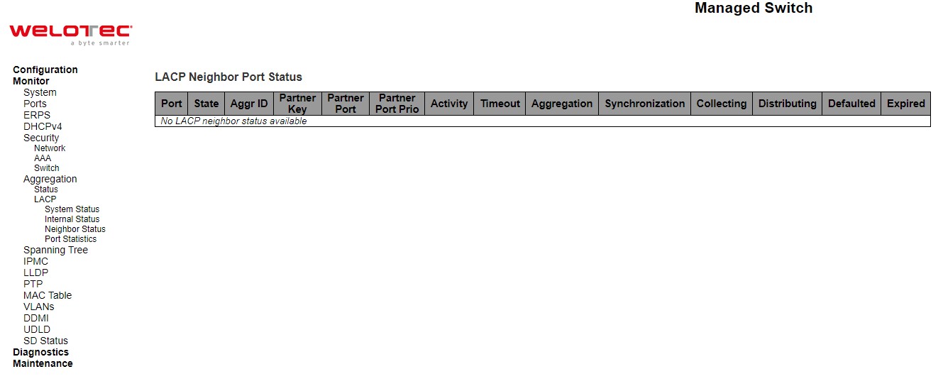
Table 3.33 Monitoring Descriptions of LACP Neighbour Port Status:
Label |
Description |
|---|---|
Port |
The switch port number. |
State |
The current port state:
|
Aggr ID |
The aggregation group ID which the port is assigned to. |
Partner Key |
The key assigned to this port by the partner. |
Partner Port |
The partner port number associated with this link. |
Partner Port Priority |
The priority assigned to this partner port. |
Activity |
The LACP mode of the group (Active or Passive). |
Timeout |
The timeout mode configured for the partner port (Fast or Slow). |
Aggregation |
Show whether the partner considers this link to be “aggregable”; i.e., a potential candidate for aggregation. |
Synchronization |
Show whether the partner considers this link to be “IN_SYNC”; i.e., it has been allocated to the correct LAG, the group has been associated with a compatible Aggregator, and the identity of the LAG is consistent with the System ID and operational Key information transmitted. |
Collecting |
Show if collection of incoming frames on this link is enabled. |
Distributing |
Show if distribution of outgoing frames on this link is enabled. |
Defaulted |
Show if the partners Receive machine is using Defaulted operational Partner information. |
Expired |
Show if that the partners Receive machine is in the EXPIRED state |
Check Auto-refresh box to refresh the page automatically. Automatic refresh occurs every 3 seconds. Click Refresh button to refresh the page immediately.
Port Statistics
This page provides an overview for LACP statistics for all ports.
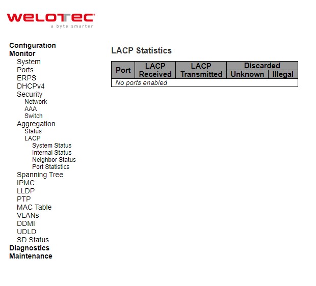
Table 3.34 Monitoring Descriptions of LACP Statistics:
Label |
Description |
|---|---|
Port |
The switch port number. |
LACP Received |
Shows how many LACP frames have been received at each port. |
LACP Transmitted |
Shows how many LACP frames have been sent from each port. |
Discarded |
Shows how many unknown or illegal LACP frames have been discarded at each port. |
Check Auto-refresh box to refresh the page automatically. Automatic refresh occurs every 3 seconds. Click Refresh button to refresh the page immediately. Click Clear button to clear the counters for the selected server. The “Pending Requests” counter will not be cleared by this operation
Spanning Tree
Bridge Status
This page provides a status overview of all STP bridge instances.
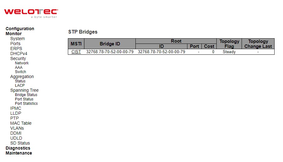
Table 3.35 Monitoring Descriptions of STP Bridges:
Label |
Description |
|---|---|
Bridge ID |
The Bridge ID of this Bridge instance. |
Root ID |
The Bridge ID of the currently elected root bridge. |
Root Port |
The switch port currently assigned the root port role. |
Root Cost |
Root Path Cost. For the Root Bridge it is zero. For all other Bridges, it is the sum of the Port Path Costs on the least cost path to the Root Bridge. |
Topology Flag |
The current state of the Topology Change Flag of this Bridge instance. |
Topology Change Last |
The time since last Topology Change occurred |
Check the Auto-refresh box to refresh the page automatically. Automatic refresh occurs every 3 seconds. Click Refresh button to refresh the page immediately.
Port Status
This page displays the STP CIST port status for physical ports of the switch.
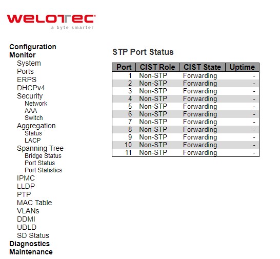
Table 3.36 Monitoring Descriptions of STP Port Status:
Label |
Description |
|---|---|
Port |
The switch port number of the logical STP port. |
CIST Role |
The current STP port role of the CIST port. The port role can be one of the following values: AlternatePort BackupPort RootPort DesignatedPort Disabled. |
CIST State |
The current STP port state of the CIST port. The port state can be one of the following values: Discarding Learning Forwarding. |
Uptime |
The time since the bridge port was last initialized |
Check the Auto-refresh box to refresh the page automatically. Automatic refresh occurs every 3 seconds. Click Refresh button to refresh the page immediately.
Port Statistics
This page displays the STP port statistics counters of bridge ports in the switch.
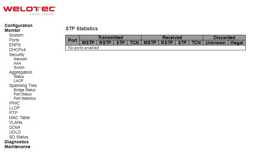
Table 3.37 Monitoring Descriptions of STP Statistics:
Label |
Description |
|---|---|
Port |
The switch port number of the logical STP port. |
Transmitted/Received MSTP |
The number of MSTP BPDU’s received/transmitted on the port. |
Transmitted/Received RSTP |
The number of RSTP BPDU’s received/transmitted on the port. |
Transmitted/Received STP |
The number of legacy STP Configuration BPDU’s received/transmitted on the port. |
Transmitted/Received TCN |
The number of (legacy) Topology Change Notification BPDU’s received/transmitted on the port. |
Discarded Unknown |
The number of unknown Spanning Tree BPDU’s received (and discarded) on the port |
Discarded Illegal |
The number of illegal Spanning Tree BPDU’s received (and discarded) on the port |
Check the Auto-refresh box to refresh the page automatically. Automatic refresh occurs every 3 seconds. Click Refresh button to refresh the page immediately.
IPMC
IGMP Snooping
Status
This page provides IGMP Snooping status.
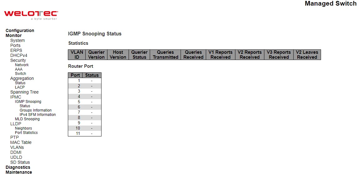
Table 3.38 Descriptions of DHCP Server Statistics Monitoring:
Label |
Description |
|---|---|
Statistics |
|
VLAN ID |
The VLAN ID of the entry. |
Querier Version |
Working Querier Version currently. |
Host Version |
Working Host Version currently. |
Querier Status |
Shows the Querier status is “ACTIVE” or “IDLE”. “DISABLE” denotes the specific interface is administratively disabled. |
Queries Transmitted |
The number of Transmitted Queries. |
Queries Received |
The number of Received Queries. |
V1 Reports Received |
The number of Received V1 Reports. |
V2 Reports Received |
The number of Received V2 Reports. |
V3 Reports Received |
The number of Received V3 Reports. |
V2 Leaves Received |
The number of Received V2 Leaves. |
Router Port |
Display which ports act as router ports. A router port is a port on the Ethernet switch that leads towards the Layer 3 multicast device or IGMP querier. Static denotes the specific port is configured to be a router port. Dynamic denotes the specific port is learnt to be a router port. Both denote the specific port is configured or learnt to be a router port. |
Port |
Switch port number |
Status |
Indicate whether specific port is a router port or not |
Check the Auto-refresh box to refresh the page automatically. Automatic refresh occurs every 3 seconds. Click Refresh button to refresh the page immediately. Click Clear button to clear all Statistics counters.
Groups Information
Entries in the IGMP Group Table are shown on this page. The IGMP Group Table is sorted first by VLAN ID, and then by group.
Each page shows up to 99 entries from the IGMP Group table, default being 20, selected through the “entries per page” input field. When first visited, the web page will show the first 20 entries from the beginning of the IGMP Group Table. The “Start from VLAN”, and “group” input fields allow the user to select the starting point in the IGMP Group Table. Clicking the Refresh button will update the displayed table starting from that or the closest next IGMP Group Table match. In addition, the two input fields will - upon a Refresh button click - assume the value of the first displayed entry, allowing for continuous refresh with the same start address. The >> will use the last entry of the currently displayed table as a basis for the next lookup. When the end is reached the text “No more entries” is shown in the displayed table. Use the |<< button to start over.
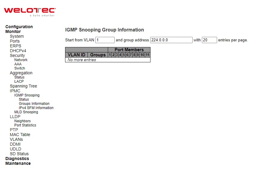
Table 3.39 Monitoring Descriptions of IGMP Snooping Group Information:
Label |
Description |
|---|---|
VLAN ID |
VLAN ID of the group. |
Groups |
Group address of the group displayed. |
Port Members |
Ports under this group |
Check the Auto-refresh box to refresh the page automatically. Automatic refresh occurs every 3 seconds. Click Refresh button to refresh the displayed table starting from the input fields. Click |<< to update the table starting from the first entry in the MVR Channels (Groups) Information Table. Click >> to updates the table, starting with the entry after the last entry currently displayed.
IPv4 SFM Information
Entries in the IGMP SFM Information Table are shown on this page. The IGMP SFM (Source-Filtered Multicast) Information Table also contains the SSM (Source-Specific Multicast) information. This table is sorted first by VLAN ID, then by group, and then by Port. Different source addresses belong to the same group are treated as single entry.
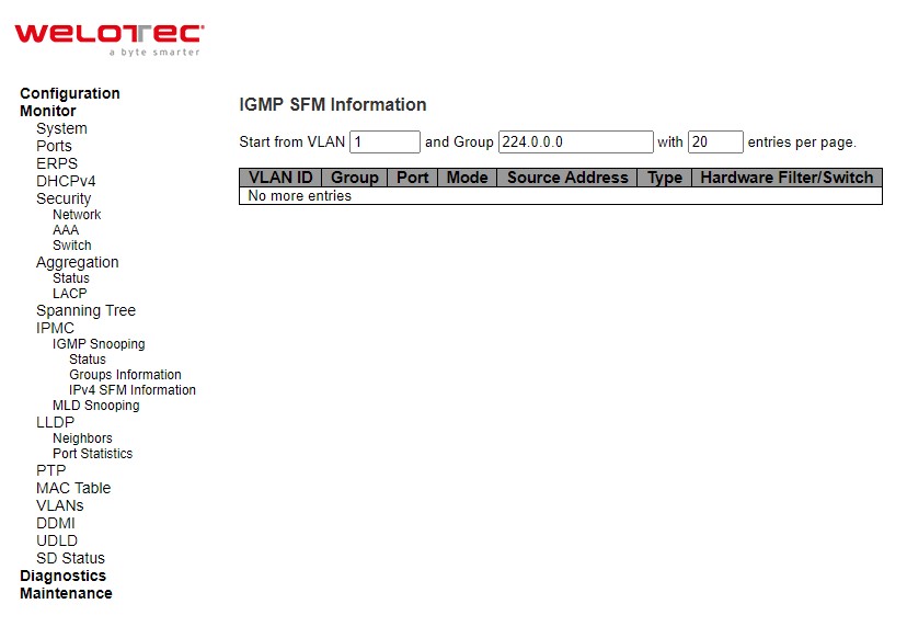
Table 3.40 Monitoring Descriptions IGMP SFM Information:
Label |
Description |
|---|---|
VLAN ID |
VLAN ID of the group. |
Group |
Group address of the group displayed. |
Port |
Switch port number. |
Mode |
Indicates the filtering mode maintained per (VLAN ID, port number, Group Address) basis. It can be either Include or Exclude. |
Source Address |
IP Address of the source. Currently, the maximum number of IPv4 source address for filtering (per group) is 8. When there is no any source filtering address, the text “None” is shown in the Source Address field. |
Type |
Indicates the Type. It can be either Allow or Deny. |
Hardware Filter/Switch |
Indicates whether data plane destined to the specific group address from the source IPv4 address could be handled by chip or not |
Check the Auto-refresh box to refresh the page automatically. Automatic refresh occurs every 3 seconds. Click Refresh button to refresh the displayed table starting from the input fields. Click |<< to update the table starting from the first entry in the IGMP SFM Information Table. Click >> to update the table, starting with the entry after the last entry currently displayed
MLD Snooping
Status
This page provides MLD Snooping status.
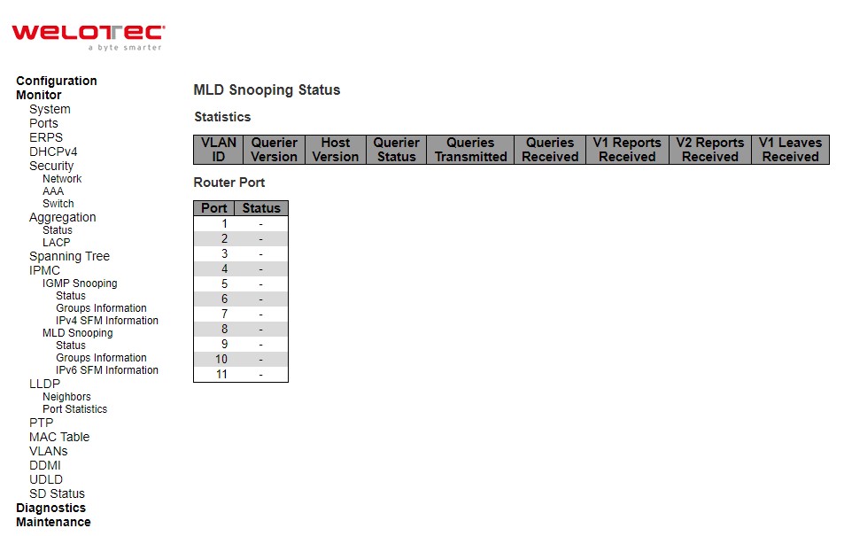
Table 3.41 Monitoring Descriptions of MLD Snooping Status:
Label |
Description |
|---|---|
VLAN ID |
The VLAN ID of the entry. |
Querier Version |
Working Querier Version currently. |
Host Version |
Working Host Version currently. |
Querier Status |
Shows the Querier status is “ACTIVE” or “IDLE”. “DISABLE” denotes the specific interface is administratively disabled. |
Queries Transmitted |
The number of Transmitted Queries. |
Queries Received |
The number of Received Queries. |
V1 Reports Received |
The number of Received V1 Reports. |
V2 Reports Received |
The number of Received V2 Reports. V1 Leaves Received |
V1 Leaves Received |
The number of Received V1 Leaves. |
Router Port |
Display which ports act as router ports. A router port is a port on the Ethernet switch that leads towards the Layer 3 multicast device or MLD querier. Static denotes the specific port is configured to be a router port. Dynamic denotes the specific port is learnt to be a router port. Both denote the specific port is configured or learnt to be a router port. |
Port |
Switch port number. |
Status |
Indicate whether specific port is a router port or not |
Check the Auto-refresh box to refresh the page automatically. Automatic refresh occurs every 3 seconds. Click Refresh button to refresh the page immediately. Click Clear button to clear all Statistics counters.
Groups Information
Entries in the MLD Group Table are shown on this page. The MLD Group Table is sorted first by VLAN ID, and then by group.
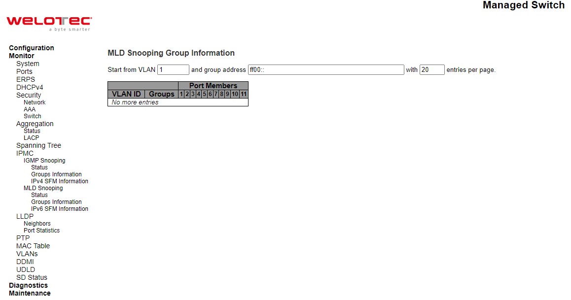
Table 3.42 Monitoring Descriptions of MLD Snooping Group Information:
Label |
Description |
|---|---|
VLAN ID |
VLAN ID of the group. |
Groups |
Group address of the group displayed. |
Port Members |
Ports under this group |
Check the Auto-refresh box to refresh the page automatically. Automatic refresh occurs every 3 seconds. Click Refresh button to refresh the displayed table starting from the input fields. Click |<< to update the table starting from the first entry in the MLD Group Table. Click >> to update the table, starting with the entry after the last entry currently displayed.
IPv6 SFM Information
Entries in the MLD SFM Information Table are shown on this page. The MLD SFM (Source-Filtered Multicast) Information Table also contains the SSM (Source-Specific Multicast) information. This table is sorted first by VLAN ID, then by group, and then by Port. Different source addresses belong to the same group are treated as single entry.
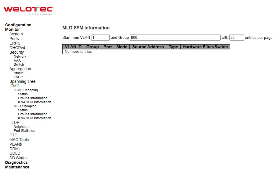
Table 3.43 Monitoring Descriptions of MLD SFM Information:
Label |
Description |
|---|---|
VLAN ID |
VLAN ID of the group. |
Group |
Group address of the group displayed. |
Port |
Switch port number. |
Mode |
Indicates the filtering mode maintained per (VLAN ID, port number, Group Address) basis. It can be either Include or Exclude. |
Source Address |
IP Address of the source. Currently, the maximum number of IPv6 source address for filtering (per group) is 8. When there is no any source filtering address, the text “None” is shown in the Source Address field. |
Type |
Indicates the Type. It can be either Allow or Deny. |
Hardware Filter/Switch |
Indicates whether data plane destined to the specific group address from the source IPv6 address could be handled by chip or not |
Check the Auto-refresh box to refresh the page automatically. Automatic refresh occurs every 3 seconds. Click Refresh button to refresh the displayed table starting from the input fields: Click |<< to update the table starting from the first entry in the MLD SFM Table. Click >> to update the table, starting with the entry after the last entry currently displayed.
LLDP
Neighbors
This page provides a status overview for all LLDP neighbours. The displayed table contains a row for each interface on which an LLDP neighbour is detected. The columns hold the following information.
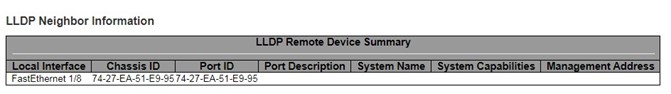
Table 3.44 Monitoring Descriptions of LLDP Neighbour Information:
Label |
Description |
|---|---|
Local Interface |
The interface on which the LLDP frame was received. |
Chassis ID |
The identification of the neighbour’s LLDP frames. |
Port ID |
The identification of the neighbour port. |
Port Description |
The port description advertised by the neighbour unit. |
System Name |
The name advertised by the neighbour unit. |
System Capabilities |
Describes the neighbour unit’s capabilities. The possible capabilities are: 1. Other 2. Repeater 3. Bridge 4. WLAN Access Point 5. Router 6. Telephone 7. DOCSIS cable device 8. Station only 9. Reserved When a capability is enabled, the capability is followed by (+). If the capability is disabled, the capability is followed by (-). |
Management Address |
The neighbour unit’s address that is used for higher layer entities to assist discovery by the network management. This could for instance hold the neighbour’s IP address |
Check the Auto-refresh box to refresh the page automatically. Automatic refresh occurs every 3 seconds. Click Refresh button to refresh this page.
Port Statistics
This page provides an overview of all LLDP traffic. Two types of counters are shown. Global counters are counters that refer to the whole switch, while local counters refer to per interface counters for the currently selected switch.
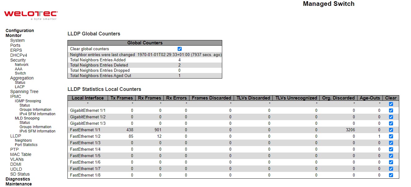
Table 3.45 Monitoring Descriptions of LLDP Global and Statistics Local Counters:
Label |
Description |
|---|---|
LLDP Global Counters |
|
Clear global counters |
If checked the global counters are cleared when Clear button is pressed. |
Neighbor entries were last changed |
Shows the time when the last entry was last deleted or added. It also shows the time elapsed since the last change was detected. |
Total Neighbors Entries Added |
Shows the number of new entries added since switch reboot. |
Total Neighbors Entries Deleted |
Shows the number of new entries deleted since switch reboot. |
Total Neighbors Entries Dropped |
Shows the number of LLDP frames dropped due to the entry table being full. |
Total Neighbors Entries Aged Out |
Shows the number of entries deleted due to Time-To-Live expiring. |
LLDP Statistics Local Counters |
|
Local Interface |
The interface on which LLDP frames are received or transmitted. |
Tx Frames |
The number of LLDP frames transmitted on the interface. |
Rx Frames |
The number of LLDP frames received on the interface. |
Rx Errors |
The number of received LLDP frames containing some kind of error. |
Frames Discarded |
If a LLDP frame is received on an interface, and the switch’s internal table has run full, the LLDP frame is counted and discarded. This situation is known as “Too Many Neighbours” in the LLDP standard. LLDP frames require a new entry in the table when the Chassis ID or Remote Port ID is not already contained within the table. Entries are removed from the table when a given interface’s link is down, an LLDP shutdown frame is received, or when the entry ages out. |
TLVs Discarded |
Each LLDP frame can contain multiple pieces of information, known as TLVs (TLV is short for “Type Length Value”). If a TLV is malformed, it is counted and discarded. |
TLVs Unrecognized |
The number of well-formed TLVs, but with an unknown type value. |
Org. Discarded |
If LLDP frame is received with an organizationally TLV, but the TLV is not supported the TLV is discarded and counted. |
Age-Outs |
Each LLDP frame contains information about how long time the LLDP information is valid (age out time). If no new LLDP frame is received within the age out time, the LLDP information is removed, and the Age-Out counter is incremented. |
Clear |
If checked the counters for the specific interface are cleared when Clear button is pressed |
Check the Auto-refresh box to refresh the page automatically. Automatic refresh occurs every 3 seconds. Click Refresh button to refresh the page immediately. Click Clear button to clear all Statistics counters.
PTP
PTP
This page allows the user to inspect the current PTP clock settings.
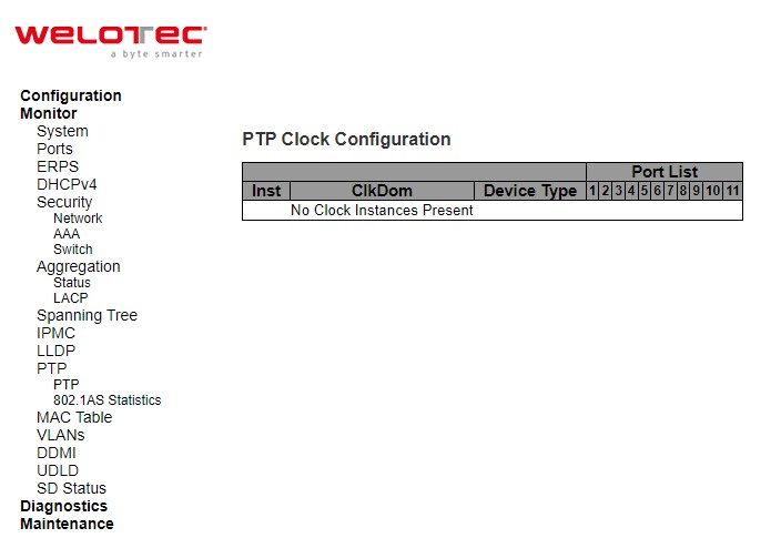
Table 3.46 Monitoring Descriptions of PTP External Clock Mode and Clock Configuration:
Label |
Description |
|---|---|
PTP Clock Configuration |
|
Inst |
Indicates the Instance of a particular Clock Instance [0..3]. Click on the Clock Instance number to monitor the Clock details. |
ClkDom |
Indicates the Clock domain used by the Instance of a particular Clock Instance [0..3]. |
Device Type |
Indicates the Type of the Clock Instance. There are five Device Types.
|
Port List |
Shows the ports configured for that Clock Instance |
Check the Auto-refresh box to refresh the page automatically. Automatic refresh occurs every 3 seconds. Click Refresh button to refresh the page immediately
802.1AS Statistics
This page allows the user to inspect the current PTP configurations, and possibly change them as well.
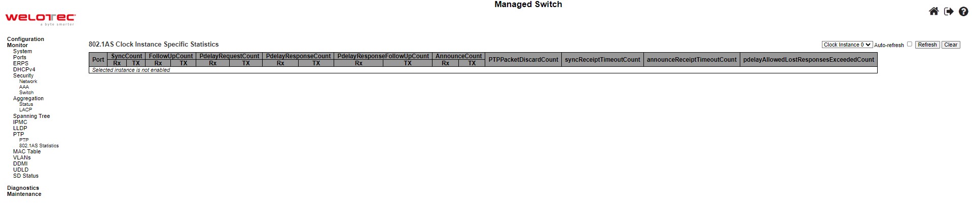
Table 3.47 Monitoring Descriptions of 802.1AS Statistics:
Label |
Description |
|---|---|
SyncCount |
A counter that increments every time when synchronization information is received. |
FollowUpCount |
A counter that increments every time when a Follow Up message is received. |
PdelayRequestCount |
A counter that increments every time when a Pdelay_Req message is received. |
PdelayResponseCount |
A counter that increments every time when a Pdelay_Resp message is received. |
PdelayResponseFollowUpCount |
A counter that increments every time when a Pdelay_Resp_Follow_Up message is received. |
AnnounceCount |
A counter that increments every time when an Announce message is received. |
PTPPacketDiscardCount |
A counter that increments every time when announce receipt timeout occurs. |
pdelayAllowedLostResponsesExceededCount |
A counter that increments every time the value of the variable lostResponses exceeds the value of the variable allowedLostResponses. |
802.1As Transmit Counters |
|
SyncCount |
A counter that increments every time synchronization information is transmitted. |
FollowUpCount |
A counter that increments every time a Follow_Up message is transmitted. |
PdelayRequestCount |
A counter that increments every time a Pdelay_Resp message is transmitted. |
PdelayResponseFollowUpCount |
A counter that increments every time a Pdelay_Resp_Follow_Up message is transmitted. |
AnnounceCount |
A counter that increments every time an Announce message is transmitted. |
PTPPacketDiscardCount |
A counter that increments every time when a PTP message is discarded. |
syncReceiptTimeoutCount |
A counter that increments every time when sync receipt timeout occurs. |
announceReceiptTimeoutCount |
A counter that increments every time when announce receipt timeout occurs. |
pdelayAllowedLostResponsesExceededCount |
A counter that increments everytime the value of the variable lostResponses exceeds the value of the variable allowedLostResponses |
MAC Table
Entries in the MAC Table are shown on this page. The MAC Table contains up to 8192 entries, and is sorted first by VLAN ID, then by MAC address.
Navigating through the MAC table, users will realize the followings. Each page shows up to 999 entries from the MAC table, default being 20, selected through the “entries per page” input field. When first visited, the web page will show the first 20 entries from the beginning of the MAC Table. The first displayed will be the one with the lowest VLAN ID and the lowest MAC address found in the MAC Table. The “Start from MAC address” and “VLAN” input fields allow the user to select the starting point in the MAC Table. Clicking the Refresh button will update the displayed table starting from that or the closest next MAC Table match. In addition, the two input fields will - upon a Refresh button click - assume the value of the first displayed entry, allowing for continuous refresh with the same start address. The >> will use the last entry of the currently displayed VLAN/MAC address pairs as a basis for the next lookup. When the end is reached the text “No more entries” is shown in the displayed table. Use the |<< button to start over.
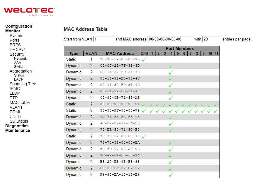
Table 3.48 Monitoring Descriptions of MAC Address Table:
Label |
Description |
|---|---|
Type |
Indicates whether the entry is a static or a dynamic entry. |
MAC address |
The MAC address of the entry. |
VLAN |
The VLAN ID of the entry. |
Port Members |
The ports that are members of the entry |
VLANs
The following describes how to navigate the VLAN Membership Status page. Each page shows up to 99 entries from the VLAN table (default being 20), selected through the “entries per page” input field. When first visited, the web page will show the first 20 entries from the beginning of the VLAN Table. The first displayed will be the one with the lowest VLAN ID found in the VLAN Table. The “VLAN” input field allows the user to select the starting point in the VLAN Table. Clicking the Refresh button will update the displayed table starting from that or the closest next VLAN Table match. The >> will use the last entry of the currently displayed VLAN entry as a basis for the next lookup. When the end is reached, the text “No data exists for the selected user” is shown in the table. Use the |<< button to start over.
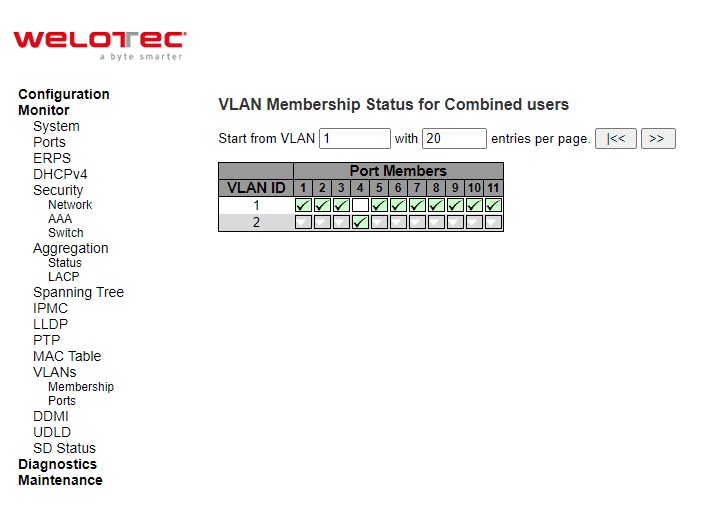
Table 3.49 Monitoring Descriptions of VLAN Membership Status for Combined Users:
Label |
Description |
|---|---|
VLAN User |
Various internal software modules may use VLAN services to configure VLAN memberships on the fly. The drop-down list on the right allows for selecting between showing VLAN memberships as configured by an administrator (Admin) or as configured by one of these internal software modules. The “Combined” entry will show a combination of the administrator and internal software modules configuration, and basically reflects what is actually configured in hardware. |
VLAN ID |
VLAN ID for which the Port members are displayed. |
Port Members |
A row of check boxes for each port is displayed for each VLAN ID. If a port is included in a VLAN, the following image will be displayed: green ✓ . If a port is in the forbidden port list, the following image will be displayed: red ✗. If a port is in the forbidden port list and at the same time attempted included in the VLAN, the following image will be displayed: red ✗. The port will not be a member of the VLAN in this case. |
Click combined buttons to select VLAN Users from this drop-down list. Check the Auto-refresh box to refresh the page automatically. Automatic refresh occurs every 3 seconds. Click Refresh button to refresh the page immediately.
Ports
This page provides VLAN Port Status.
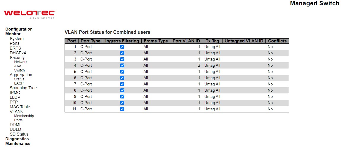
Table 3.50 Monitoring Descriptions of VLAN Port Status for Combined Users:
Label |
Description |
|---|---|
VLAN User |
Various internal software modules may use VLAN services to configure VLAN port configuration on the fly. |
Port |
The logical port for the settings contained in the same row. |
Port Type |
Shows the port type (Unaware, C-Port, S-Port, S-Custom-Port.) that a given user wants to configure on the port. The field is empty if not overridden by the selected user. |
Ingress Filtering |
Shows whether a given user wants ingress filtering enabled or not. The field is empty if not overridden by the selected user. |
Frame Type |
Shows the acceptable frame types (All, Tagged, Untagged) that a given user wants to configure on the port. The field is empty if not overridden by the selected user. |
Port VLAN ID |
Shows the Port VLAN ID (PVID) that a given user wants the port to have. The field is empty if not overridden by the selected user. |
Tx Tag |
Shows the Tx Tag requirements (Tag All, Tag PVID, Tag UVID, Untag All, Untag PVID, Untag UVID) that a given user has on a port. The field is empty if not overridden by the selected user. |
Untagged VLAN ID |
If Tx Tag is overridden by the selected user and is set to Tag or Untag UVID, then this field will show the VLAN ID the user wants to tag or untag on egress. The field is empty if not overridden by the selected user. |
Conflicts |
Two users may have conflicting requirements to a port’s configuration. For instance, one user may require all frames to be tagged on egress while another requires all frames to be untagged on egress. |
Click combined buttons to select VLAN Users from this drop-down list. Check the Auto-refresh box to refresh the page automatically. Automatic refresh occurs every 3 seconds. Click Refresh button to refresh the page immediately
DDMI
Overview
Display DDMI overview information on this page.
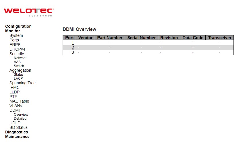
Table 3.51 Monitoring Descriptions of DDMI Overview:
Label |
Description |
|---|---|
Port |
DDMI port. |
Vendor |
Indicates Vendor name SFP vendor name. |
Part Number |
Indicates Vendor PN Part number provided by SFP vendor. |
Serial Number |
Indicates Vendor SN Serial number provided by vendor. |
Revision |
Indicates Vendor rev Revision level for part number provided by vendor. |
Data Code |
Indicates Date code Vendor’s manufacturing date code. |
Transceiver |
Indicates Transceiver compatibility |
Detailed
Display DDMI detailed information on this page. DDMI is an acronym for Digital Diagnostics Monitoring Interface. It provides an enhanced digital diagnostic monitoring interface for optical transceivers which allows real time access to device operating parameters.
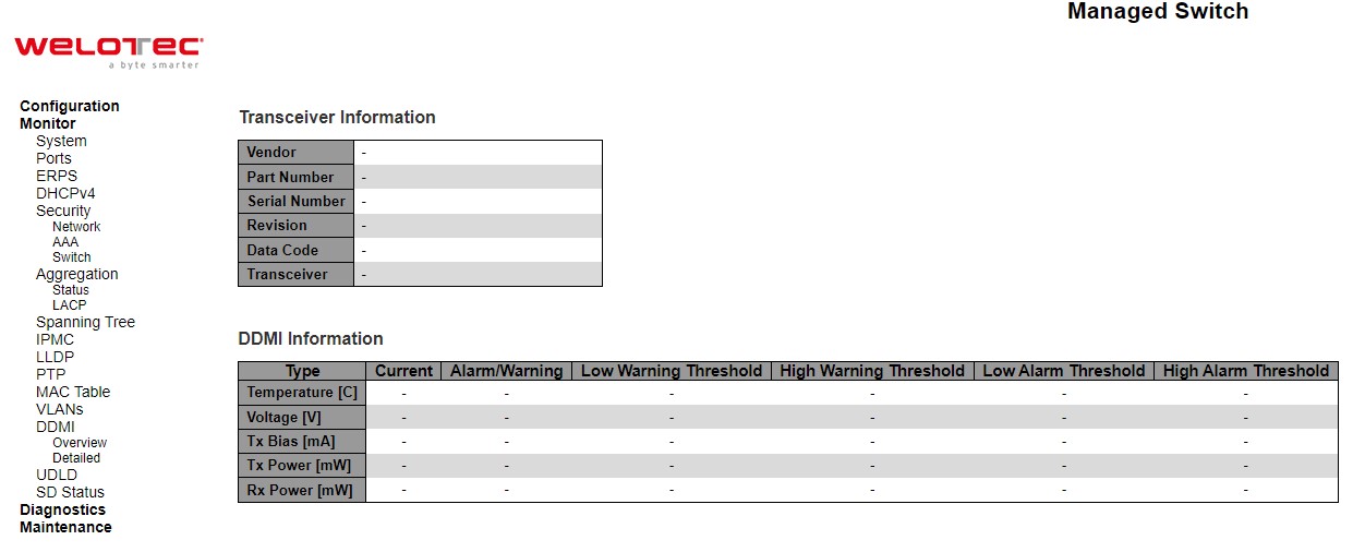
Table 3.52 Monitoring Descriptions of DDMI Detailed:
Label |
Description |
|---|---|
Transceiver Information |
|
Vendor |
Indicates SFP vendor name. |
Part Number |
Indicates part number provided by SFP vendor. |
Serial Number |
Indicates serial number provided by SFP vendor. |
Revision |
Indicates revision level for part number provided by SFP vendor. |
Data Code |
Indicates vendor’s manufacturing date code. |
Transceiver |
Indicates SFP transceiver compatibility. |
DDMI Information |
|
Current |
The current value of temperature, voltage, Tx bias, Tx power, and Rx power. |
Alarm/Warning |
Indicates whether there is an alarm or warning. |
Low Warning Threshold |
The low warning threshold value of temperature, voltage, Tx bias, Tx power, and Rx power. |
High Warning Threshold |
The high warning threshold value of temperature, voltage, Tx bias, Tx power, and Rx power. |
Low Alarm Threshold |
The low alarm threshold value of temperature, voltage, Tx bias, Tx power, and Rx power. |
High Alarm Threshold |
The high alarm threshold value of temperature, voltage, Tx bias, Tx power, and Rx power |
UDLD
This page displays the UDLD status of the ports. UDLD is an acronym for Uni Directional Link Detection. UDLD protocol monitors the physical configuration of the links between devices and ports that support UDLD. It detects the existence of unidirectional links. Its functionality is to provide mechanisms useful for detecting one-way connections before they create a loop or other protocol malfunction. RFC 5171 specifies a way at data link layer to detect Uni directional link.
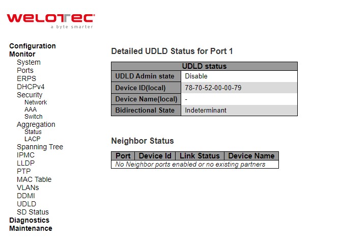
Table 3.53 Monitoring Descriptions of Detailed UDLD Status for Port 1 and Neighbour Status:
Label |
Description |
|---|---|
Detailed UDLD Status |
|
UDLD Admin State |
The current port state of the logical port. Enabled if any of state (Normal, Aggressive) is Enabled. |
Device ID (local) |
The ID of Device. |
Device Name(local) |
Name of the Device. |
Bidirectional State |
The current state of the port. |
Neighbour Status |
|
Port |
The current port of neighbour device. |
Device ID |
The current ID of neighbour device. |
Link Status |
The current link status of neighbour port. |
Device Name |
Name of the Neighbour Device |
The port select box ![][285]determines which port is affected by clicking the buttons. Check the Auto-refresh box to refresh the page automatically. Automatic refresh occurs every 3 seconds. Click Refresh button to refresh the page immediately