Configuring with a Web Browser
There are three ways to configure Welotec’s Industrial Managed Ethernet Switch: Web browser, Telnet console, and Serial console. How to access the industrial managed switch through web browser is explained in Chapter 2 through Chapter 5. There are only a few differences among these three methods. The web browser and the telnet console methods allow users to access the switch over the Internet or the Ethernet LAN, while the serial console method requires a serial cable connection between the console and the switch. Users are recommended to configure the switch via a web browser because of its user-friendly interface.
Next, we will proceed to use a web browser to introduce the managed switch’s functions. It is recommended to use Microsoft Edge 103, Firefox 44, Chrome 48 or later versions. Below is a list of default factory settings. This information will be used during the login process. Make sure that the computer accessing the switch are in the same subnet. That is the computer has an IP address and the subnet mask same as the switch. Please pay attention when inputting the username and password, as they are case sensitive.
IP Address: 192.168.2.1
Subnet Mask: 255.255.0.
Default Gateway: 0.0.0.0
User Name: admin
Password: RSAES@Welotec
Before users can access the configuration, they have to log in. This can simply be done in the following steps.
Launch a web browser.
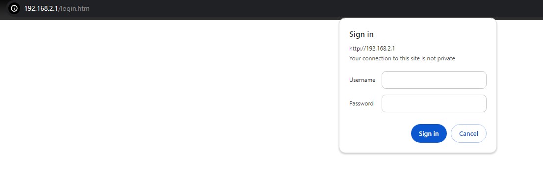
Type in the switch IP address (default: http://192.168.2.1). As shown in Figure 2.1. another IP-Adress (e.g. 10.0.50.1) may be used depending on your setup.
Note: When the user name and the password are left empty, the login prompt will not show.
The user can enter a Username and a Password to access the managed switch. Then, clicking on the Sign in button.
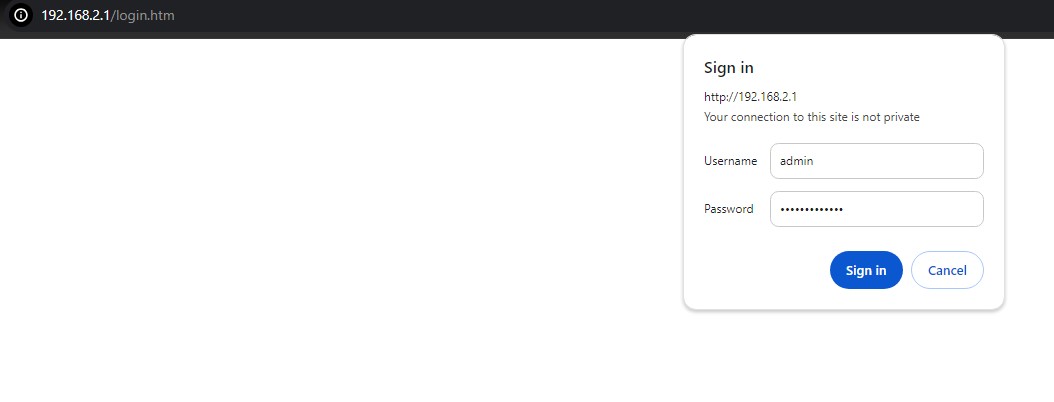
If the user entered wrong passwords, users can try to re-enter the new username and password again until it is correct. Or users can simply click the Cancel button to forfeit the process.
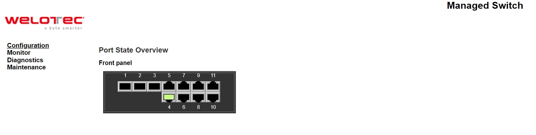
If the login process was success, the user will be presented with the Port State Overview webpage which shows the front panel of the managed switch as shown in Figure 2.3.
System
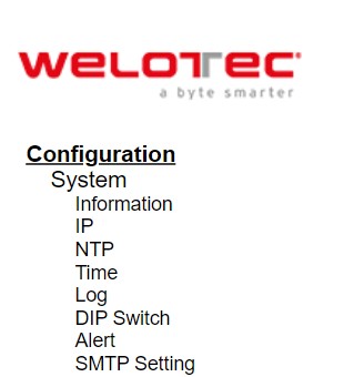
This section describes how users can configure system information in details. Figure 2.4 shows submenus under the Configuration⭢System main menu.
Information
This subsection describes how users can assign system’s details to the Welotec’s switch. There are three fields in this System Information Configuration webpage: System Contact, System Name, and System Location. By entering this unique and relevant system information, it will help identifying one specific switch among all the others in the network. However, the switch must support a SNMP protocol. Figure 2.5 shows the System Information Configuration Webpage to an RSAES managed switch model. Please click the “Save” button to update the information on the switch. Clicking on the Reset button will undo any changes made locally and revert to previously save values. Table 2.1 summarizes the device information setting descriptions and corresponding default factory settings.
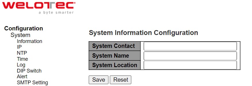
Table 2.1 Description of the System Information Configuration:
Label |
Description |
Factory Default |
|---|---|---|
System Contact |
Provides contact information for maintenance. Enter the name of whom to contact in case a problem occurs. The allowed string length is 0 to 255, and the allowed content is the ASCII characters from 32 to 126. |
Null |
System Name |
Specifies a particular role or application of different switches. The name entered here will also be shown in Welotec’s Device Management Utility. By convention, this is the node’s fully-qualified domain name. A domain name is a text string drawn from the alphabet (A-Za-z), digits (0-9), minus sign (-). No space characters are permitted as part of a name. The first character must be an alpha character. And the first or last character must not be a minus sign. The allowed string length is 0 to 255. |
Null |
System Location |
The physical location of this node (e.g.,telephone closet, 3rd floor). The allowed string length is 0 to 255, and the allowed content is the ASCII characters from 32 to 126. |
Null |
IP
In this subsection, the user may modify network settings on Internet Protocol (IP) for the managed switch. This subsection is divided into three parts: IP Configuration, IP Interfaces, and IP Routes, as shown in Table 2.7. First, the IP Configuration part is related to how the managed switch will be operated as Host. The IP Interfaces part is related to IP Address configuration and DHCP configuration for both IPv4 and IPv6. Finally, the IP Routes part contains the routing table that provides information about the network destination, gateway, next hop, and distance.
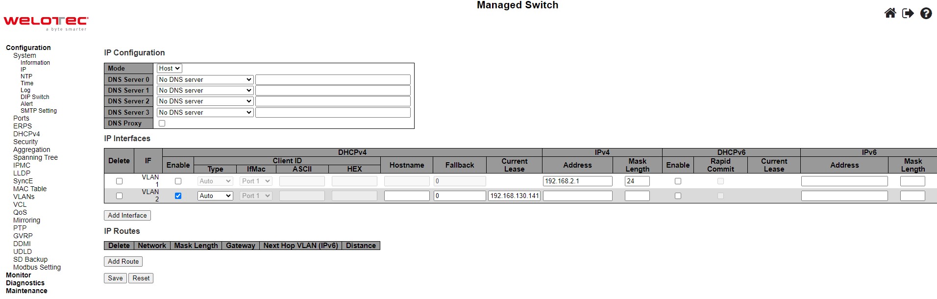
The first part as shown in Figure 2.6 allows the user to set the operating mode of the managed switch. The user can enter up to four DNS Servers. A DNS (domain name system) proxy allows clients to set up device as a DNS proxy server. A DNS proxy improves domain lookup performance by caching previous lookups. A typical DNS proxy processes DNS queries by issuing a new DNS resolution query to each name server that it has detected until the hostname is resolved. Table 2.2 provides detailed description of each option in this part which is also called basic setting.
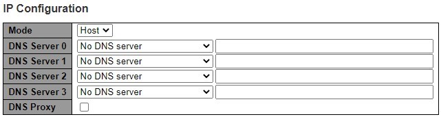
Table 2.2 Description of Basic Settings:
Label |
Description |
|---|---|
Mode |
Configure the IP stack to act as a Host, where IP traffic between interfaces will not be routed. |
DNS Server |
This setting controls the DNS name resolution done by the switch. |
DNS Proxy |
When DNS proxy is enabled, system will relay DNS requests to the currently configured DNS server, and reply as a DNS resolver to the client devices on the network. |
The second part of IP Setting section is the IP Interface part as shown in Figure 2.8. The user can choose to enable DHCP (Dynamic Host Configuration Protocol) for DHCPv4 and/or DHCPv6 by checking the box behind it. That is the IP address and related information can be automatically obtained from a DHCP server in the local network thus reducing the work for an administrator. By disabling this function (DHCP’s box is unchecked), the user has an option to setup the static IP address and related fields manually. If DHCP is disabled, the user should enter the IP addresses and Max Length (subnet mask) under IPv4 and/or IPv6 columns. Table 2.3 provides detailed description of each option in this part of IP Interfaces.

Table 2.3 Description of IP Interfaces’ Options:
Label |
Description |
|---|---|
Delete |
Select this option to delete an existing IP interface. |
IF |
The VLAN associated with the IP interface. Only ports in this VLAN will be able to access the IP interface. This field is only available for input when creating a new interface |
DHCPv4 Enabled |
Enable the DHCPv4 client by checking this box. If this option is enabled, the system will configure the IPv4 address and mask of the interface using the DHCPv4 protocol. |
DHCPv4 Client ID Type |
This specified which of the three types below, i.e. IfMac, ASCII or HEX, shall be used for the Client Identifier. See RFC-2132 section 9.14. |
DHCPv4 Client ID ifMac |
The interface name of DHCP client identifier. When DHCPv4 client is enabled and the client identifier type is ‘ifmac’, the configured interface’s hardware MAC address will be used in the DHCP option 61 field. |
DHCPv4 Client ID ASCII |
The ASCII string of DHCP client identifier. When DHCPv4 client is enabled and the client identifier type is ‘ascii’, the ASCII string will be used in the DHCP option 61 field. |
DHCPv4 Client ID HEX |
The hexadecimal string of DHCP client identifier. When DHCPv4 client is enabled and the client identifier type ‘hex’, the hexadecimal value will be used in the DHCP option 61 field. |
DHCPv4 Hostname |
The hostname of DHCP client. If DHCPv4 client is enabled, the configured hostname will be used in the DHCP option 12 field. When this value is empty string, the field use the configured system name plus the latest three bytes of system MAC addresses as the hostname. |
DHCPv4 Fallback |
The number of seconds for trying to obtain a DHCP lease. After this period expires, a configured IPv4 address will be used as IPv4 interface address. A value of zero disables the fall-back mechanism, such that DHCP will keep retrying until a valid lease is obtained. Legal values are 0 to 4294967295 seconds. |
DHCPv4 Current Lease |
For DHCP interfaces with an active lease, this column shows the current interface address, as provided by the DHCP server. |
IPv4 Address |
The IPv4 address of the interface in dotted decimal notation. |
IPv4 Mask Length |
The IPv4 network mask, in number of bits (prefix length). Valid values are between 0 and 30 bits for an IPv4 address. |
DHCPv6 Enable |
Enable the DHCPv6 client by checking this box. If this option is enabled, the system will configure the IPv6 address of the interface using the DHCPv6 protocol. |
DHCPv6 Rapid Commit |
Enable the DHCPv6 Rapid-Commit option by checking this box. If this option is enabled, the DHCPv6 client terminates the waiting process as soon as a Reply message with a Rapid Commit option is received. |
DHCPv6 Current Lease |
For DHCPv6 interface with an active lease, this column shows the interface address provided by the DHCPv6 server. |
IPv6 Address |
The IPv6 address of the interface. An IPv6 address is in 128-bit records represented as eight fields of up to four hexadecimal digits with a colon separating each field (:). For example, fe80::215:c5ff:fe03:4dc7. The symbol :: is a special syntax that can be used as a shorthand way of representing multiple 16-bit groups of contiguous zeros; but it can appear only once. |
IPv6 Mask Length |
The IPv6 network mask, in number of bits (prefix length). Valid values are between 1 and 128 bits for an IPv6 address. |
The third part of IP Setting section is the IP Routes part as shown in Figure 2.9. Description of each field or option is summarized in Table 2.4. Please click on the Save button to update the IP configuration on the switch. A system reboot is required after each update, so the new network settings can take effect. The user will need to manually update the new IP address in the URL field of the web browser if the IP address of the managed switch is changed.
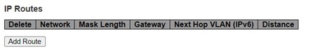
Table 2.4 Description of IP Routes’ Options:
Label |
Description |
|---|---|
Delete |
Select this option to delete an existing IP route. |
Network |
The destination IP network or host address of this route. Valid format is dotted decimal notation or a valid IPv6 notation. A default route can use the value 0.0.0.0or IPv6 :: notation. |
Mask Length |
The destination IP network or host mask, in number of bits (prefix length). It defines how much of a network address that must match, in order to qualify for this route. Valid values are between 0 and 32 bits respectively 128 for IPv6 routes. Only a default route will have a mask length of 0 (as it will match anything). |
Gateway |
The IP address of the IP gateway. Valid format is dotted decimal notation or a valid IPv6 notation. Gateway and Network must be of the same type. |
Next Hop VLAN (IPv6) |
The VLAN ID (VID) of the specific IPv6 interface associated with the gateway. |
Distance |
The distance value of the route entry is used to provide the priority information routing protocols to routers. When two or more different routing protocols are involved and have the same destination, the distance value can be used to select the best path. |
NTP
Welotec’s industrial managed switch has internal calendar (date) and clock (or system time) which can be set manually or automatically. Figure 2.10 shows the Network Time Protocol (NTP) configuration webpage. Here, users can automatically set the device’s time by first selecting Enabled from the drop-down menu of Mode field. Then, users must enter the IP or Domain address of up to the total of five NTP servers: Server1, Server2, Server3, Server4, and Server 5. This allows the device to synchronise date and time with one of the NTP server. First, it will be synchronized with the Server 1. If it failed to respond, the device will select the second priority server or Server 2 to synchronize time with. If the Server 2 failed to respond, the device will then contact the third priority server or Server 3. This goes on until the device gets the respond from the NTP server, or none of them is respond. If any field is NULL, the device will not contact that server and continue contacting other lower priority servers instead.
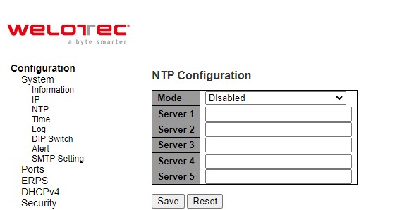
The detailed description of each field is provided in Table 2.5.
Table 2.5 Descriptions of the NTP Settings:
Label |
Description |
Factory Default |
|---|---|---|
Mode |
Select to enable or disable an automatically setting of the device time. This option will disable or enable network time protocol (NTP) daemon inside the managed switch which allows this managed device to synchronize its clock with other NTP servers. |
Disabled |
Server 1 |
Sets the first IP or Domain address of NTP Server; e.g., time.nist.gov. |
NULL |
Server 2 |
Sets the second IP or Domain address of NTP Server. |
NULL |
Server 3 |
Sets the third IP or Domain address of NTP Server. Switch will locate the 3rd NTP Server if the 2nd NTP Server fails to connect. |
NULL |
Server 4 |
Sets the fourth IP or Domain address of NTP Server. Switch will locate the 4th NTP Server if the 3rd NTP Server fails to connect. |
NULL |
Server 5 |
Sets the fifth IP or Domain address of NTP Server. Switch will locate the 5th NTP Server if the 4th NTP Server fails to connect. |
NULL |
Time
This Time webpage allows the user to configure the time zone and daylight saving for the managed switch. There are three setting parts within this webpage: System Time Configuration, Time Zone Configuration, and Daylight Saving Time Configuration.
The first part : System Time Configuration, users are allowed to set the device’s system time by manual. Table 2.6 summarizes the descriptions of options in system time configuration.
The second part : Time Zone Configuration, users are allowed to set the device’s time zone. By clicking the drop-down list of Time Zone field, users can select the device’s local time zone or Manual Setting option*.* In the Hours and Minutes fields, users can enter the number of hours and minutes of the device’s time that is offset from the local time zone when users selected Manual Setting option. Table 2.7 summarizes the descriptions of options in time zone configuration.
The third part : Daylight-Saving Time Configuration, if the switch is deployed in a region where daylight saving time is practiced (see note below for explanation), please select the Recurring or Non-Recurring options for Daylight Saving Time field within the Daylight-Saving Time Configuration box. Then, users will have to enter the Start Time settings, End Time settings, and Offset settings in minute(s). Note that the Start Time settings and End Time setting will be different between the Recurring and Non-Recurring options. Recurring option means that the configuration of daylight saving will be repeated very year. On the other hand, non-recurring option means that the daylight saving will be repeated only on the specified years. Table 2.8 summarizes the descriptions of options in daylight saving time configuration.
Note:
Daylight Saving Time: In certain regions (e.g., US), local time is adjusted during the summer season in order to provide an extra hour of daylight in the afternoon, and one hour is usually shifted forward or backward.
NTP: Network Time Protocol is used to synchronize the computer systems’ clocks with a standard NTP server: Examples of two NTP servers are time.nist.gov and time-A.timefreq.bldrdoc.gov.
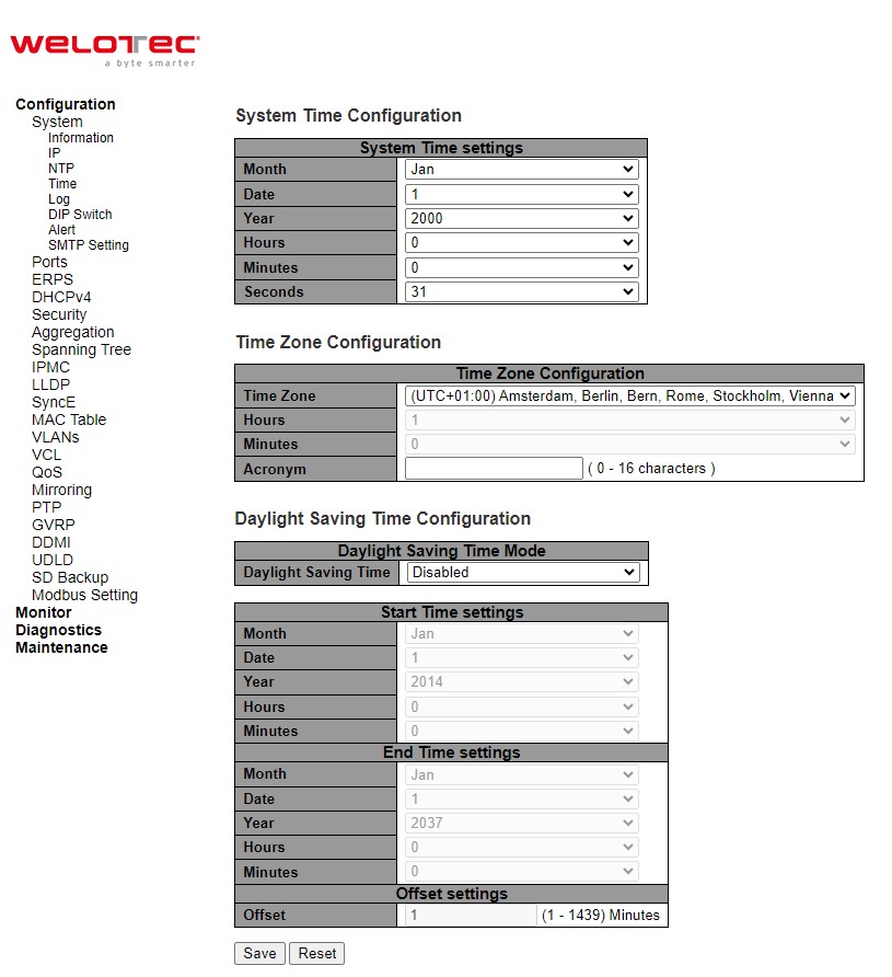
Table 2.6 Description of System Time Configuration:
Label |
Description |
|---|---|
Month |
Select the month of system time |
Date |
Select the date of system time |
Year |
Select the year of system time |
Hours |
Select the starting hour of system time |
Minutes |
Select the starting minute of system time |
Seconds |
Select the starting second of system time |
Table 2.7 Description of Time Zone Configuration:
Label |
Description |
|---|---|
Time Zone |
Lists various Time Zones worldwide. Select appropriate Time Zone from the drop down and click Save to set. The ‘Manual Setting’ options is used for the specific time zone which is excluded from the options list. |
Hours |
Number of hours offset from UTC. The field only available when Time Zone is set to Manual Setting. |
Minutes |
Number of minutes offset from UTC. The field only available when Time Zone is set to Manual Setting. |
Acronym |
User can set the acronym of the time zone. This is a User configurable acronym to identify the time zone. |
Table 2.8 Description of Daylight-Saving Time Configuration:
Label |
Description |
|---|---|
Daylight Saving Time |
This is used to set the clokc forward or backward according to the configurations set below for a defined Daylight-Saving Time duration. |
Recurring Configuration |
|
Start Time settings |
Week - Select the starting week number. |
End time settings |
Week - Select the ending week number. |
Offset settings |
Offset - Enter the number of minutes to add during Daylight Saving Time. (Range: 1 to 1439) |
Non-Recurring Configuration |
|
Start Time settings |
Month - Select the starting month. |
End time settings |
Month - Select the ending month. |
Offset settings |
Offset - Enter the number of minutes to add during Daylight Saving Time. (Range: 1 to 1439) |
Log
Figure 2.12 shows System Log configuration setting webpage. System Log or syslog keeps records of messages or events that are related to the overall functionalities of the managed switch. Here the users can enable how the log will be delivered to other system. It can be sent to a remote log server. Select Enabled from the drop-down list of the Server Mode field if users want the system log to be saved in the remote log server, or select Disabled to disable server mode operation. The users need to select the log level and provide the IP address of a remote log server. Please click on the Save button after finishing the setup or Reset button to disregard all changes made locally and revert to previously saved values. Table 2.9 describes the details of parameters setting for the system log. Type of syslog level include: Error, Warning, Notice, and Informational.
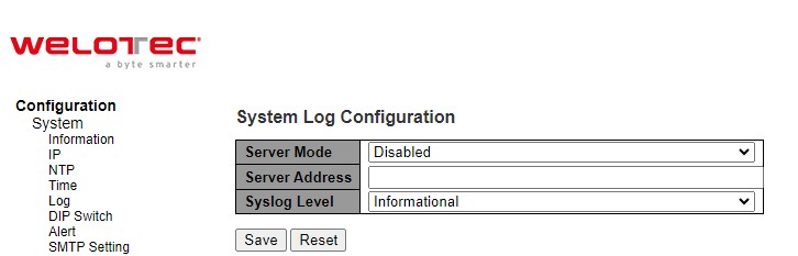
Table 2.9 Descriptions of the System Zone Configuration:
Field |
Detailed description of mode |
|---|---|
Server Mode |
Indicates the server mode operation. When the mode is enabled, the syslog message will send out to syslog server. The syslog protocol is based on UDP communication and received on UDP port 514 and the syslog server will not send acknowledgments back sender since UDP is a connectionless protocol and it does not provide acknowledgments. The syslog packet will always send out even if the syslog server does not exist. Possible modes are: |
Server Address |
Indicates the IPv4 host address of syslog server. If the switch provides DNS feature, it also can be a domain name. |
Syslog Level |
Indicates what kind of message will send to syslog server. Possible modes are: |
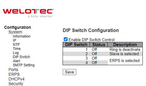
DIP Switch
This section describes the DIP Switch Configuration. Click the Enable DIP Switch Control box to enable it. The DIP switch 1 on/off means Ring is activated/deactivated. The DIP switch 2 on/off means Master is selected/deselected, and Slave is deselected/selected. When the DIP Switch 3 and 4 are on, nothing (N/A) is selected. When the DIP switch 3 and 4 are off, ERPS is selected. Webpage for configuring the system DIP switch is shown in Figure 2.13. Click Save button to update the DIP Switch Configuration.
Alert
This webpage allows the users to configure how each type of the power status alarm events will be sent or notify the users. Power Status Alarms keep track of power status of the switch based on the available input connectors.
RSAES supports two to three power sources. In the example, Power1 and Power2 are illustrated as shown in Figure 2.14. Users can enable a notification of each power source separately. Also, they can get notifications through many methods including Relay, Alarm LED, and E-mail by selecting Enabled in any of these fields. Click Save button to let the setting take effect, or click Reset button to change back to the previously saved values.
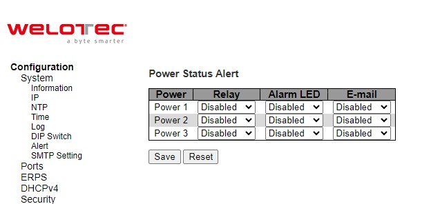
Table 2.10 summarizes the Power Status Alarm event selection.
Table 2.10 Descriptions of Power Status Alarm Event Selection:
Label |
Description |
Factory Default |
|---|---|---|
Power |
Indicate specific power supply such as Power 1 and Power 2 |
- |
Relay |
Options: Disabled, Power On, or Power Off |
Disabled |
Alarm LED |
Options: Disabled, Power On, or Power Off |
Disabled |
Options: Disabled, Power On, or Power Off |
Disabled |
SMTP Setting
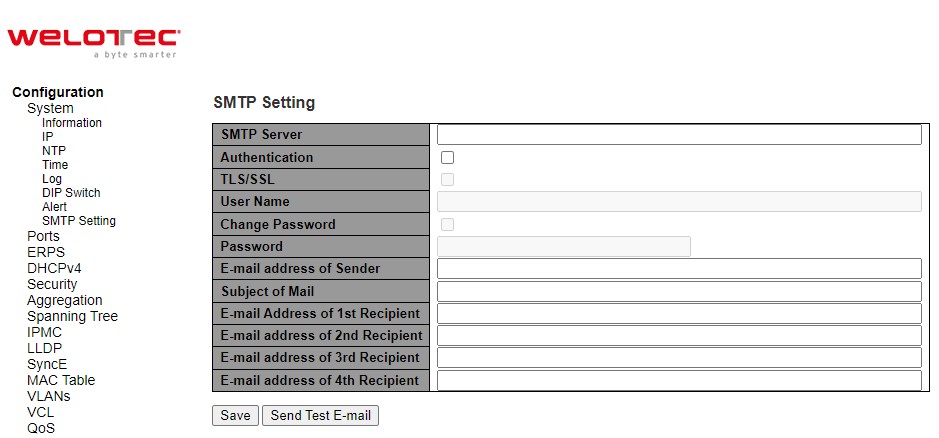
Simple Mail Transfer Protocol (SMTP) is an internet standard for e-mail transmission across IP networks. In case any warning events occur, the system can send an alarm message (e.g., Link Status and System Log) to users by e-mail. As shown in Figure 2.15, users can enable/disable server’s authentication, input user name and password if enabled, and edit email address of the sender and four recipients. The total of four recipients are allowed to receive an e-mail.
An example of SMTP Setting is shown in Figure 2.16. When users select the box behind the Authentication field, TLS field as well as User Name and Change Password fields are enabled. Users can configure e-mail address of sender, so that the recipient can reply back to the correct person in charge. Also, users can configure the subject of email, so that it can be easily distinguishable from the other e-mails. At last, users can edit e-mail addresses of all four recipients in the order shown in the e-mail. After entering all the necessary fields, please click on the Save button to allow the setting to take effect. Note that users can test sending an e-mail by simply clicking on the Send Test E-mail button. The description of each SMTP Setting parameter is summarized in Table 2.11.
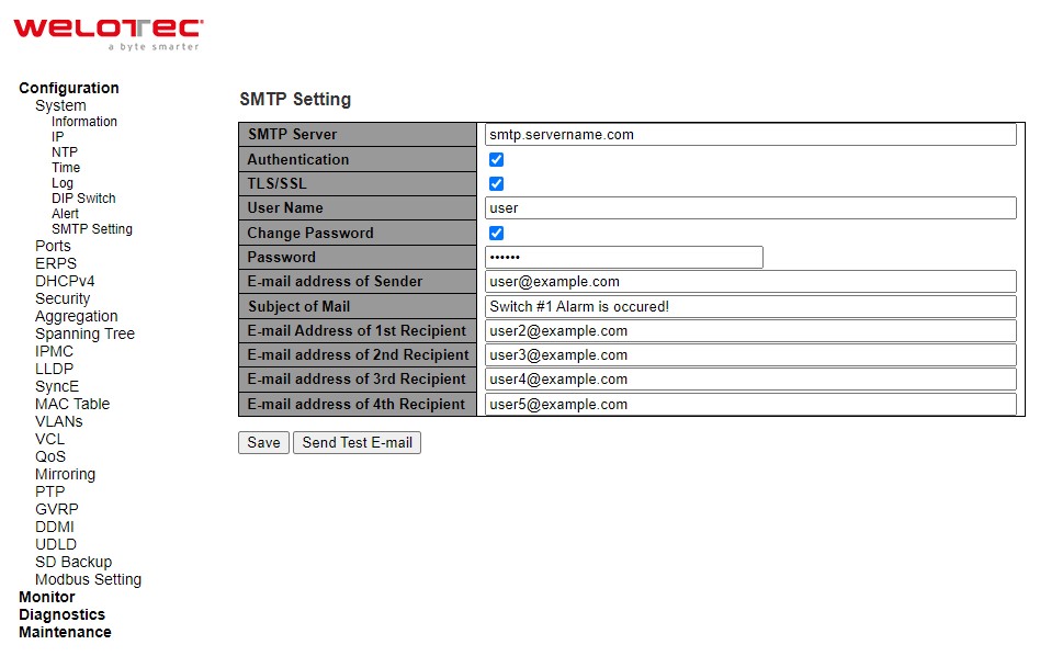
Table 2.11 Descriptions of SMTP Setting:
Label |
Description |
Factory Default |
|---|---|---|
SMTP Server |
Configure the IP address of an out-going e-mail server |
NULL |
Authentication |
By checking on the box, users Enable or disable an authentication login. If enabled, users need an authentication to access the SMTP server. Thus, the users will also need to setup User Name and Password to connect to the SMTP server |
Disable |
TLS/SSL |
Enable or disable Transport Layer Security (TLS)/ Secure Sockets |
Disable |
User Name |
Set the user name (or account name) to login for authentication. Max. 31 characters. |
NULL |
Change Password |
Enable the checkbox if user need to set or change account password. If the checkbox is disabled, the account password will remain the old one. (If the password has not be set before, it will be NULL) |
Disable |
Password |
Set the account password for login/authentication. Max. 31 characters. |
NULL |
E-mail Address of Sender |
Configure the sender E-mail address |
NULL |
Subject of Mail |
Type the subject of this warning message. Max. 63 characters. |
NULL |
E-mail Address of 1st Recipient |
Set the first receiver’s E-mail address. |
NULL |
E-mail Address of 2nd Recipient |
Set the second receiver’s E-mail address. |
NULL |
E-mail Address of 3rd Recipient |
Set the third receiver’s E-mail address. |
NULL |
E-mail Address of 4th Recipient |
Set the fourth receiver’s E-mail address. |
NULL |
Save |
Save these modifications on the managed switch. |
- |
Send Test E-mail |
Send a test email to recipient(s) above to check accuracy. |
- |
Ports
Port Setting webpage is shown in Figure 2.17. The users can check the state of each port through Link column. Red color means port is down while green color means port is up. Users can also check the Warning status of the port. In the speed column, users can check the Current speed and configure a new speed through Configured column. The possible physical layer connections of each port are listed on the Adv Duplex and Adv speed column. The port’s duplexing (Duplex) can be either Full duplex (Fdx) or Half duplex (Hdx). The Half duplex option allows one-way communication at a time, while the Full duplex option allows simultaneous two-way communication. The transmission Speed of each port can be chosen from the dropdown list which could be 10, 100, and 1000 Mbps.
On the next column, user can select to enable/disable Flow Control for each port. The Flow Control mechanism can be enabled to avoid packet loss when congestion occurs. Within this column, there are Curr Rx and Curr Tx sub-columns, where users can check the status of flow control on the receiving and transmitting link, respectively.
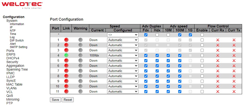
Table 2.12 Descriptions of Port Configuration:
Field label |
Subfield Label |
Description |
Factory Default |
|---|---|---|---|
Port |
Indicate port number. e.g., ranging from 1 to 11. In the first row, port * will show all possible configurable options for the device. |
- |
|
Link |
Show link status. Red colour for port down, and green colour for port up. |
- |
|
Warning |
Indicate a warning when there is a problem with the port. Different colours are used to indicate the severity of port problem. |
Grey colour |
|
Speed |
Current |
Show current speed of the port. e.g., 100 fdx for 100 Mbps full duplex. If port is currently down, this field will show “down”. |
- |
Speed |
Configured |
Select any available link speed for the given siwtch port. Only speeds supported by the specific port is shown. Possible speeds are: |
Automatic |
Adv Duplex |
Auto |
When duplex is set as auto i.e. auto negotiation, the port will only advertise the specified duplex as either Fdx or Hdx to the link partner. By default, port will advertise all the supported duplexes if the Duplex is Auto. |
|
Adv Duplex |
Fdx |
Full-duplex mode of the link. Click a checkbox to enable the option. |
- |
Adv Duplex |
Hdx |
Half-duplex mode of the link. Click a checkbox to enable the option. |
- |
Adv Speed |
Auto |
When speed is set as auto i.e. auto negotiation, the port will only advertise the specified speeds (10M, 100M, 1G) to the link partner. By default, port will advertise alle supported speeds if speed is set as Auto. |
|
Adv Speed |
10M |
Click to enable 10 Mbps link speed for this port. |
- |
Adv Speed |
100M |
Click to enable 100 Mbps link speed for this port. |
- |
Adv Speed |
1G |
Click to enable 1 Gbps link speed for this port. |
- |
Flow Control |
Auto |
When Auto speed is selected on a port, this section indicates the flow control capability that is a vertised to the link partner. |
|
Flow Control |
Enable |
The Flow Control mechanism can be enabled to avoid packet loss when congestion occurs. |
|
Flow Control |
Curr Rx |
Symbol √ for showing that flow control is active on the receiving traffic. |
|
Flow Control |
Curr Tx |
Symbol √ for showing that flow control is active on the transmitting traffic. |
|
 for showing that flow control is not active on the receiving traffic.
ERPS
Ethernet Ring Protection Switching (ERPS) is a protocol for Ethernet layer network rings. The protocol specifies the protection mechanism for sub-50 ms delay time. ERPS provides highly reliable and stable protection in the ring topology, and it never forms loops, which can affect network operation and service availability.
An ERPS ring consists of interconnected Layer 2 switching devices configured with the same control VLAN. The major ring is a closed ring, whereas a sub-ring is a non-closed ring. The major ring and sub-ring can be configured through type field.
In the Ethernet ring, loops can be avoided by guaranteeing that traffic may flow on all but one of the ring links at any time. This particular link is called Ring Protection Link (RPL). A control message called Ring Automatic Protection Switch (RAPS) coordinates the activities of switching on/off the RPL. Under normal conditions, this link is blocked by the designated Ethernet Ring Node called RPL Owner Node to ensure that there is no loop formed for the Ethernet traffic. The node at the other end of the RPL is known as RPL Neighbor Node. In case an Ethernet ring failure occurs, the RPL Owner Node will be responsible for unblocking its end of the RPL to allow RPL to be used as a backup link. The RPL is the backup link when one link failure occurs. Other ring ports called common port will help monitoring the status of the directly connected ERPS link and send RAPS PDUs to notify the other ports of its link status changes.
In case that users do not want their clients to detect the fault and would like sometimes to rectify the problem, users may use the Holdoff timer. If the fault occurs, the fault is not immediately sent to ERPS until the Holdoff timer expires.
If an RPL owner port is unblocked due to a link or node recovery after its faulty, the involved port may not be changed to Up state immediately since it may cause network flapping. To prevent this problem, in revertive switching, the node where the RPL owner port resides starts the wait to restore (WTR) timer after receiving a RAPS No Request (NR) message. If the node receives a RAPS Signal Fail (SF) message before the timer expires, it will terminate the WTR timer. Otherwise, the RPL owner will block its own port, and send out RAPS (no request or NR, root blocked or RB) messages to inform the other nodes of the link or node recovery and starts the Guard timer. Before the Guard timer expires, other nodes do not process any RAPS (NR) messages to avoid receiving out-of-date RAPS (NR) messages. After the Guard timer expires, if the other nodes still receive RAPS (NR) messages, the nodes set their recovered ports on the ring to the Forwarding state. In non-revertive switching, the WTR timer is not started, and the original faulty link is still blocked. ERPSv1 supports only revertive switching. ERPSv2 supports both revertive and non-revertive switching.
Control messages of each ERPS ring (e.g., R-APS PDUs) are transmitted through a configuration of a control VLAN. For an ERPS ring that is already configured a control VLAN, when users add a port to the ERPS ring, the port is automatically added to the control VLAN. Different ERPS rings cannot be configured with the same control VLAN ID. The control VLAN must be mapped to an Ethernet Ring Protection (ERP) instance, so that ERPS forwards or blocks the VLAN packets based on blocking rules, protecting the ring network from broadcast storms.
Figure 2.19 shows the ERPS Configuration webpage. Table 2.13 summarizes the descriptions of columns in EPRS Configuration’s table.
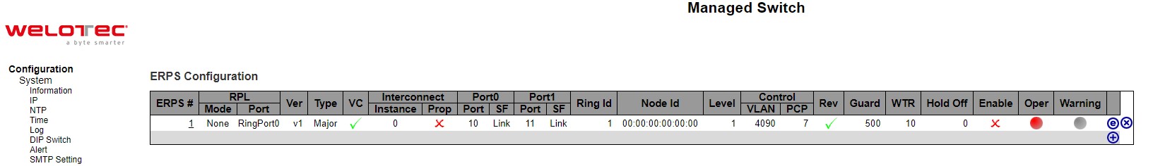
Label |
Description |
|---|---|
ERPS |
The ID of ERPS. Valid range 1 - 64. |
RPL Mode |
Ring Protection Link mode. Possible values: |
RPL Port |
Indicates whether it is port0 or port1 that is the Ring Protection Link. Not used if RPL Mode is None. |
Ver |
ERPS protocol version. v1 and v2 are supported. |
Type |
Type of ring. Possible values: |
VC |
Controls whether to use a Virtual Channel with a sub-ring. |
Interconnect Instance |
For a sub-ring on an interconnection node, this must reference the instance ID of the ring to which this sub-ring is connected. |
Interconnect Prop |
Controls whether the ring referenced by Interconnect Instance shall propagate R-APS flush PDUs whenever this sub-ring’s topology changes. |
Port0/Port1 Interface |
Interface index of ring protection Port0/Port1. |
Port0/Port1 SF |
Selects whether Signal Fail (SF) comes from the link state of a given interface, or from a Down-MEP. Possible values: |
Ring Id |
The Ring ID is used - along with the control VLAN - to identify R-APS PDUs as belonging to a particular ring. |
Node Id |
The Node ID is used inside the R-APS specific PDU to uniquely identify this node (switch) on the ring. |
Level |
MD/MEG Level of R-APS PDUs we transmit. |
Control VLAN |
The VLAN on which R-APS PDUs are transmitted and received on the ring ports. |
Control PCP |
The PCP value used in the VLAN tag of the R-APS PDUs. |
Rev |
Revertive (true) or Non-revertive (false) mode. |
Guard |
Guard time in ms. Valid range is 10 - 2000 ms. |
WTR |
Wait-to-Restore time (WTR) in seconds. Valid range 1 - 720 sec. |
Hold Off |
Hold off time in ms. Value is rounded down to 100ms precision. Valid range is 0 - 10000 ms. |
Enable |
The administrative state of this APS ERPS. Check to make it function normally and uncheck to make it cease functioning. |
Oper |
The operational state of ERPS instance. |
Warning |
Operational warnings of ERPS instance. |
Please click  to start configuring the ERPS. After clicking the , Figure 2.20 below will be appeared.
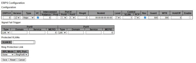
Table 2.14 shows the descriptions of each field and subfields in the ERPs configuration webpage in details.
Table 2.14 Descriptions of ERPS Configuration Webpage:
Field Label |
Subfield Label |
Description |
Factory Default |
|---|---|---|---|
ERPS |
Configure ERPS number to indicate a ring. Ranging from 1 to 64. |
0 |
|
Version |
Indicate the version that ERPS protocol is using. Two options are available: v1 and v2. |
V2 |
|
Type |
Indicate type of ERPS ring. There are three options: Major, Sub, Intersub. |
Major |
|
VC |
Controls whether to use a Virtual Channel with a sub-ring. The Virtual Channel that’s used to pass through R-APS message packet of subring. User must add control VLAN of sub-ring to each ring ports of Major-ring. If selected, the virtual channel is enabled. |
Clicked |
|
Interconnect |
Instance |
For a sub-ring on an interconnection node, this must reference the instance ID of the ring to which this sub-ring is connected. Ethernet Ring Protection (ERP) Instance to forwards or blocks the VLAN packets based on blocking rules. |
0 |
Interconnect |
Prop |
Controls whether the ring referenced by Interconnect Instance shall propagate R-APS flush PDUs whenever this sub-ring’s topology changes. |
Unclicked |
Port If |
Port0 |
Select which port on the managed switch will be on Ring Port0. Ranging from 1 to maximum number of ports. |
1 |
Port If |
Port1 |
Select which port on the managed switch will be on Ring Port1. Ranging from 1 to maximum number of ports. |
1 |
RingID |
Indicate ring identification number, ranging from 1 to 9999. The Ring ID is used - along with the control VLAN - to identify R-APS PDUs as belonging to a particular ring. |
1 |
|
NodeID |
The Node ID is used inside the R-APS specific PDU to uniquely identify this node (switch) on the ring. Enter a MAC address manually. |
00:00:00:00:00:00 |
|
Level |
MD/MEG Level of R-APS PDUs we transmit. Ranging from 0 to 7. |
7 |
|
Control |
VLAN |
The VLAN on which R-APS PDUs are transmitted and received on the ring ports. Specify the virtual local area network that this static MAC belongs to, ranging from 1 to 4096. |
1 |
Control |
PCP |
The PCP value used in the VLAN tag of the R-APS PDUs. Priority Code Point within the Ethernet frame header. PCP 0 is the lowest priority and 7 is the highest priority. |
7 |
Rev |
Revertive (true) or Non-revertive (false) mode. Click/Unclick to enable the revertive/non-revertive switching. |
Clicked |
|
Guard |
Set the guard time of the ring. Range is from 10 to 2000 ms. |
500 |
|
WTR |
Set the wait-to-restore (WTR) time of the ring in seconds. Lower value has lower protection time. Range of the WTR Timer is from 1 to 720 seconds. |
300 |
|
HoldOff |
Set the holdoff time of the ring. Range is from 0 to 10000 ms. |
0 |
|
Enable |
The administrative state of this ERPS. Check to make it function normally and uncheck to make it cease functioning. |
Unclicked |
|
VLAN ID |
Indicate Identification number of VLAN (Virtual Local Area Network). VLANs which are protected by this ring instance. At least one VLAN must be protected. Specify as a comma separated list of vlan numbers or vlan ranges. Ex.: 1,4,7,30-70. |
NULL |
|
RPL Mode |
There are three types of Ring Protection Link (RPL0 mode: None, Owner, Neighbour) where: |
None |
|
RPL Port |
Indicates whether it is port0 or port1 that is the Ring Protection Link. Not used if RPL Mode is None. |
RingPort0 |
Click Save button to save changes. Click Reset button to undo any changes made locally and revert to previously saved values. Click Cancel button to return to the previous page; any changes made locally will be undone.
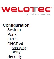
DHCPv4
Welotec’s RSAES managed switch can act as a DHCPv4 (Dynamic Host Configuration Protocol over IP version 4) server in the local network. By enabling this function in the managed switch, an IPv4 addresses and related fields will be automatically assigned and delivered by the DHCPv4 server running inside the managed switch to other network devices connected to the managed switch. Under this Configuration⭢DHCPv4 menu, there are two submenus, Snooping and Relay as shown in Figure 2.21. The following subsections will describe them in more details.
Snooping
A rogue DHCP (Dynamic Host Control Protocol) server may be set up by an attacker in the network to provide falsify network configuration to a DHCP client such as wrong IP address, in-correct subnet mask, malicious gateway, and malicious DNS server. The purpose of DHCP spoofing attack may be to redirect the traffic of the DHCP client to a malicious domain and try to eavesdrop the traffic or simply try to prevent a successful network connection establishment. To protect against a network security attack of rogue DHCP server or DHCP spoofing attack, Welotec’s RSAES provide DHCP Snooping feature. When this feature is enabled on specific port(s) of RSAES managed switch, the RSAES will allow the DHCP messages from trusted ports to pass through while it will discard or filter the DHCP messages from untrusted ports. To enable the DHCP Snooping feature, select the Enabled option from the dropdown menu behind the Snooping Mode option under the DHCP Snooping Configuration webpage as shown in Figure 2.22. By default, all interfaces of RSAES are untrusted for DHCP Snooping. To configure specific port(s) as trusted port(s), simply select the Trusted option under the Mode column for that particular Port(s). Finally, click the Save button at the bottom of the webpage to activate the DHCP Snooping on the selected port(s). Click Reset button to undo any change made locally and revert to previously saved values. Table 2.15 describes the options of DHCP Snooping Configuration.
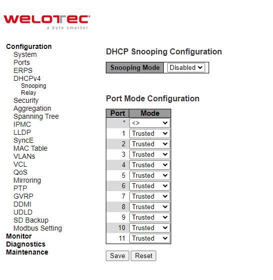
Table 2.15 Description of DHCP Snooping Configuration:
Field Label |
Description |
Factory Default |
|---|---|---|
Snooping Mode |
Indicates the DHCP snooping mode operation. Possible modes are: |
Disabled |
Port Mode Configuration |
Indicates the DHCP snooping port mode. Possible port modes are: |
Trusted |
Relay
A DHCP relay agent is a small program that relays DHCP/BOOTP messages between clients and servers on different subnets. DHCP/BOOTP relay agents are parts of the DHCP and BOOTP standards and function according to the Request for Comments (RFCs). It stores the incoming interface IP address in the GIADDR field of the DHCP packet. The DHCP server can use the value of GIADDR field to determine the assigned subnet. For such condition, please make sure the switch configuration of VLAN interface IP address and PVID (Port VLAN ID) correctly.
A relay agent relays DHCP/BOOTP messages that are broadcast on one of its connected physical interfaces, such as a network adapter, to other remote subnets to which it is connected by other physical interfaces. Figure 2.23 shows the DHCP Relay configuration webpage. Users can enable the DHCP Relay by selecting the Enabled box behind the Relay Mode option. Then, users can enter a Relay server’s IP address in the Relay Server field.
Users also have a choice to enable the DHCP Relay Information Mode. If it is enabled, the switch will insert information about the client’s network location into the packet header of the DHCP request, which is coming from the client on an untrusted interface. Then, the switch will send the modified request to the DHCP server. The DHCP server will inspect the information in the packet header and use it to generate the IP address or other parameters for the client. When the DHCP server returns the response to the switch, the switch will have an option to Replace, Keep, and Drop the information from the response packet and forward it to the client. After finishing the DHCP Relay setup, please click on the Save button to allow the change to take effect.
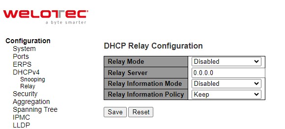
Table 2.16 Description of DHCP Relay Configuration:
Field Label |
Description |
Factory Default |
|---|---|---|
Relay Mode |
There are two modes here: Disabled or Enabled. Click the dropdown box to deactivate or activate the relay mode. |
Disabled |
Relay server |
Enter an IPv4 address of the DHCP relay server. |
0.0.0.0 |
Relay Information Mode |
There are two modes here: Disabled and Enabled. Click the dropdown list to deactivate or activate the information mode of the DHCP relay server. |
Disabled |
Relay Information Policy |
Set the information policy for the DHCP relay server. There are three modes here: Replace, Keep, and Drop. When DHCP relay information mode operation is enabled, if the agent receives a DHCP message that already contains relay agent information it will enforce the policy. The ‘Replace’ policy is invalid when relay information mode is disabled. |
Keep |
Security
Security Configuration of Welotec’s RSAES managed switch consists of three main parts: Switch, Network, and AAA. There are a number of submenus for each of these main security configuration parts as shown in Figure 2.24.
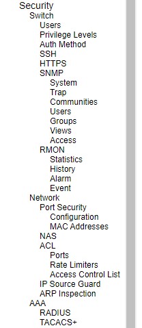
Switch
The first submenu under Configuration⭢Security is the Switch menu as shown in Figure 2.25. There are other submenus under this Switch menu which are Users, Privilege Levels, Auth Method, SSH, HTTPS, SNMP, and RMON. The following subsections will explain each of these menus in more details.
Switch Users
A simple way of providing terminal access control in your network device (managed switch) is to use passwords and assign privilege levels. Password protection restricts access to a network or network device. Privilege levels define what commands users can enter after they have logged into a network device. RSAES managed switch uses privilege levels to provide password security for different levels of switch operation. The privilege level of the user is ranging from 0 to 15. If the user has the privilege level value of 15, it means that the user is granted the full control of the device, which is being an administrator. The system maintenance, such as software upload and factory defaults, need a user privilege level of 15. Guest account usually is assigned with the privilege level 5, and has the read-only access. Whereas, a standard user usually is assigned with the privilege level of 10 and has the read-write access.
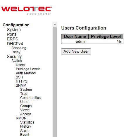
When users first enter this Users Configuration webpage, users will see an overview of the current users. The user overview webpage consists of User Name and Privilege Level columns, as shown in Figure 2.26. Currently the only way to login as another user on the web server of the managed switch is to close and reopen the web browser. Table 2.17 provides explanation for the User Configuration webpage.
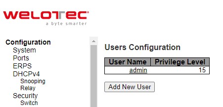
Table 2.17 Description of Users Configuration:
Field Label |
Description |
|---|---|
User Name |
The name identifying the user. This is also a link to Add/Edit User. |
Privilege Level |
The privilege level of the user. The allowed range is 0 to 15. If the privilege level value is 15, it can access all groups, i.e., that is granted the fully control of the device. But other values need to refer to each group privelege level. User`s privilege should be same or greater than the group privilege level to have the access of that group. By default setting, most groups privilege level 5 has the read-only access and privilege level 10 has the read-write access. And the system maintence (software upload, factory defaults and etc.) need user privilege level 15. Generally, the privilege levl 15 can be used for an administrator account, privilege level 10 for a standard user account and privilege level 5 for a guest account. |
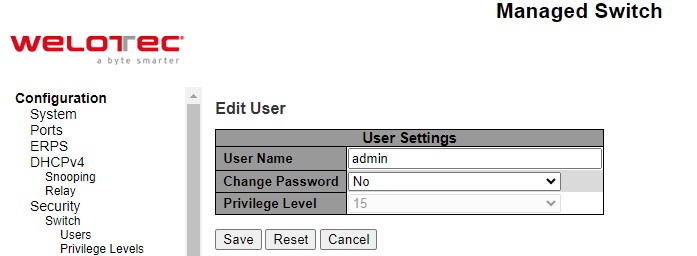
There is also a hyperlink to Add/Edit User in each username. Users can also click Add New User button to add a new user. After clicked, the webpage in Figure 2.27 will be shown. Table 2.18 summarizes the descriptions of the Add User webpage. Figure 2.28 shows an example of Edit User webpage.
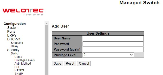
Table 2.18 Descriptions of Users Configuration – After Clicked Add New User Button:
Label |
Description |
Factory Default |
|---|---|---|
Username |
A string identifying the user name that this entry should belong to. The allowed string length is 1 to 31. The valid username allows letters, numbers and underscores. |
NULL |
Password |
The password of the user. The allowed string length is 0 to 31. Any printable characters including space is accepted. |
NULL |
Password (again) |
Re-enter the password for the user. |
NULL |
Privilege Level |
The privilege level of the user. The allowed range is 0 to 15. If the privilege level value is 15, it can access all groups, i.e., that is granted the fully control of the device. But other values need to refer to each group privelege level. User`s privilege should be same or greater than the group privilege level to have the access of that group. By default setting, most groups privilege level 5 has the read-only access and privilege level 10 has the read-write access. And the system maintence (software upload, factory defaults and etc.) need user privilege level 15. Generally, the privilege levl 15 can be used for an administrator account, privilege level 10 for a standard user account and privilege level 5 for a guest account. |
0 |
Switch Privilege Levels
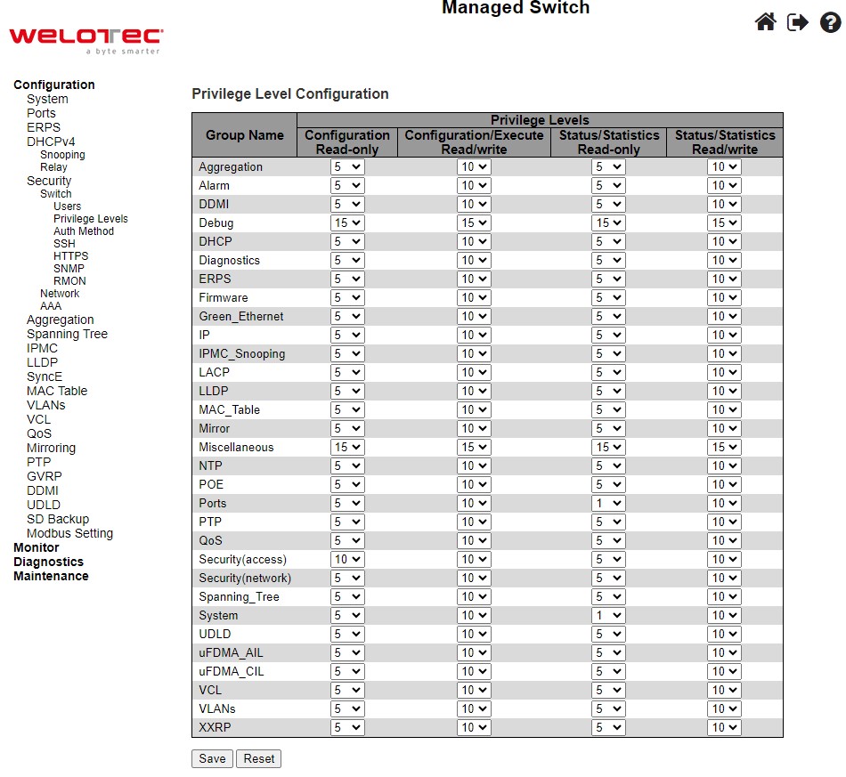
This subsection describes on the Privilege Level Configuration webpage as shown in Figure 2.29. The user can customize the privilege level in the table on this webpage.
Group Name is the name identifying the privilege group. In most cases, a privilege level group consists of a single module (e.g., LACP, RSTP or QoS), but a few of them contains more than one. Table 2.19 shows examples of some group name in details:
Table 2.19 Examples of Group Name:
Label |
Description |
|---|---|
System |
Contact, Name, Location, Time zone, Daylight Saving Time, Log. |
Security |
Authentication, System Access Management, Port (contains Dot1x port, MAC based and the MAC Address Limit), ACL, HTTPS, SSH, ARP Inspection, IP source guard. |
IP |
Everything except ‘ping’. |
Port |
Everything except ‘VeriPHY’. |
Diagnostics |
‘ping’ and ‘VeriPHY’. |
Maintenance |
CLI- System Reboot, System Restore Default, System Password, Configuration Save, Configuration Load and Firmware Load. Web- Users, Privilege Levels and everything in Maintenance. |
Debug |
Only present in CLI. |
Privilege Levels in every group has an authorization Privilege level for the following sub groups: Configuration Read only, Configuration/Execute Read-Write, Status/Statistics Read-only, Status/Statistics Read-Write (e.g., for clearing of statistics). User Privilege should be the same or greater than the authorization Privilege level to have the access to that group.
Switch Auth Method
The authentication section allows you to configure how a user is authenticated when he/she logs into the switch via one of the management client interfaces. Note that management client interfaces are console, telnet, ssh, and http. There are three separated tables in this webpage: Authentication Method Configuration, Command Authorization Method configuration, and Accounting Method Configuration webpage, as shown in Figure 2.30. In the Authentication Method Configuration, users can configure how a user is authenticated when he/she logs into the switch via one of the management client interfaces. In Command Authorization Method configuration, users can configure the limitation of the CLI commands available to a user. In the Accounting Method Configuration webpage, users can configure command and exec (login) accounting. Table 2.20 shows descriptions of these methods in details. Please click Save button for a change to take effect, or click Reset button to undo any changes made locally and revert to previously saved values.
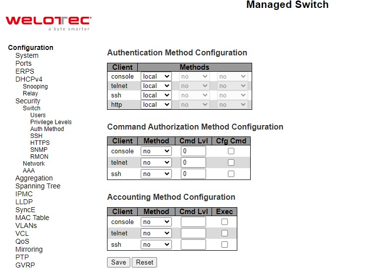
Table 2.20 Descriptions of Switch Authentication Method:
Label |
Description |
Factory Default |
|---|---|---|
Authentication Method Configuration |
||
Client |
The management client for which the configuration below applies, which consists of console, telnet, ssh. |
- |
Methods |
Set to one of the following values: |
local, no, no |
Command Authorization Method configuration |
||
Client |
The management client for which the configuration below applies. |
- |
Method |
Method can be set to one of the following values: |
no |
Cmd Lvl |
Authorize all commands with a privilege level higher than or equal to this level. Valid values are in the range 0 to 15. |
0 |
Cfg Cmd |
Also authorize configuration commands. |
Unclicked |
Accounting Method Configuration webpage |
||
Client |
The management client for which the configuration below applies. |
- |
Method |
Method can be set to one of the following values: |
no |
Cmd Lvl |
Enable accounting of all commands with a privilege level higher than or equal to this level. Valid values are in the range 0 to 15. Leave the field empty to disable command accounting. |
NULL |
Exec |
Enable exec (login) accounting. |
Unclicked |
Switch SSH
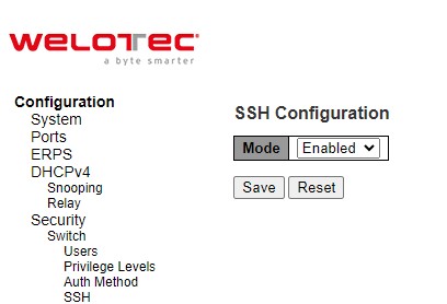
Users can enabled/disabled SSH (Secure Shell) mode through SSH Configuration webpage, as shown in Figure 2.31. Here, users can select Enabled/Disabled from the drop-down list of Mode field. Please click Save button for a change to take effect or Reset button to undo any changes made locally and revert to previously saved values.
HTTPS
Users can enabled/disabled HTTPS (Hypertext Transfer Protocol over Secure Socket Layer) mode through HTTPS Configuration Webpage, as shown in Figure 2.32. HTTPS provide authentication and encrypted communication and is widely used on the World Wide Web for security-sensitive communication such as payment transactions and corporate logons. HTTPS is really just the use of Secure Socket Layer (SSL) as a sublayer under its regular HTTP application layering. (HTTPS uses port 443 instead of HTTP port 80 in its interactions with the lower layer, TCP/IP.) SSL uses a 40-bit key size for the RC4 stream encryption algorithm, which is considered an adequate degree of encryption for commercial exchange.
There are total of four fields: Mode, Automatic Redirect, Certificate Maintain, and Certificate Status. In the Mode field, users can select Enabled/Disabled the HTTPs mode. In the Automatic Redirect field, users can select to Enabled/Disabled this mode. When it is enabled, a HTTP connection will be automatically redirected to be a HTTPS connection. Note here that the browser may not allow to redirection if the browser does not trust the switch certificate. In such case, users need to initialize the HTTPS connection manually. For the Certificate Maintain field, users can choose type of operation whether to do nothing (None), delete the current certificate (Delete), upload a new certificate (Upload), and generate a new certificate (Generate). In the last field, Certificate Status, it displays the current status of certificate on the switch. Please click Save button for a change to take effect or Reset button to undo any changes made locally and revert to previously saved values.
If the user selects the Upload option for Certificate Maintain field, the webpage will be updated with additional fields which are Certificate Pass Phrase, Certificate Upload, and File Upload as shown in Figure 2.33. Table 2.21 summarizes the descriptions of fields in HTTPS Configuration webpage.
Note that to upload a certificate PEM file into the switch, the file should contain the certificate and private key together. If users have two separated files for saving certificate and private key, users can use the Linux cat command to combine them into a single PEM file. For example, cat my.cert my.key > my.pem. The RSAES certificate is recommended since most of the new version of browsers has removed support for DSA in certificate
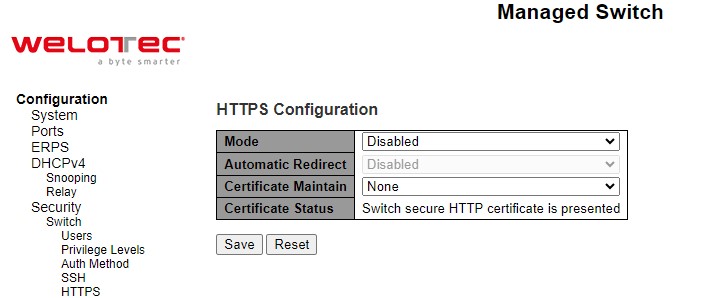
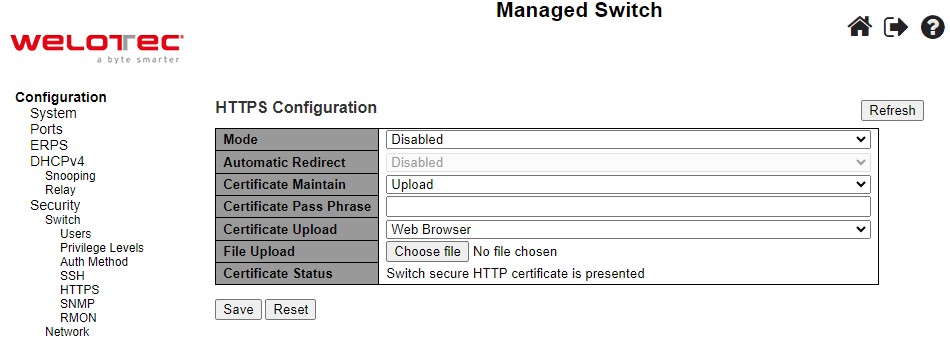
Table 2.21 Description of HTTPS Configuration Webpage:
Label |
Description |
Factory Default |
|---|---|---|
Mode |
Indicate the HTTPS mode operation. |
Disabled |
Automatic Redirect |
Indicate the HTTPS redirect mode operation. It is only significant when “HTTPS Mode Enabled” is selected. When the redirect mode is enabled, the HTTP connection will be redirected to HTTPS connection automatically. Note that the browser may not allow the redirect operation due to the security consideration unless the switch certificate is trusted to the browser. You need to initialize the HTTPS connection manually for this case. |
Disabled |
Certificate Maintain |
Indicate the operation of certificate maintenance. |
None |
Certificate Pass Phrase |
Enter the pass phrase in this field if your uploading certificate is protected by a specific passphrase. |
- |
Certificate Upload |
Upload a certificate PEM file into the switch. The file should contain the certificate and private key together. If you have two separated files for saving certificate and private key. Use the Linux cat command to combine them into a single PEM file. For example, cat my.cert my.key > my.pem. Note that the RSAES certificate is recommended since most of the new version of browsers has removed support for DSA in certificate, e.g. Firefox v37 and Chrome v39. |
|
Certificate Status |
Display the current status of certificate on the switch. Possible statuses are: |
Switch secure HTTP certificate is presented. |
SNMP System
Simple Network Management Protocol (SNMP) is a protocol for managing devices on IP networks. It exposes management data in the form of variables on the managed systems which describe the system configuration. These variables can then be queried or defined by the users. The SNMP is used by network management system or third-party software to monitor devices such as managed switches in a network to retrieve network status information and to configure network parameters. The Welotec’s managed switch support SNMP and can be configured in this section.
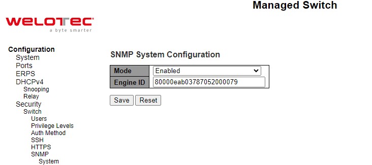
In this submenu, SNMP system can be configured as shown in Figure 2.34. There are two fields here: Mode and Engine ID. In Mode, users can select Enabled/Disabled from the dropdown list to enable SNMP mode operation. In Engine ID, it indicates the SNMPv3 engine ID. The string must contain an even number (in hexadecimal format) with number of digits between 10 and 64, but all-zeros and all-‘F’s are not allowed. Change of the Engine ID will clear all original local users. The default setting is 80000eab030200c14df2e0.
Please click Save button for a change to take effect or Reset button to undo any changes made locally and revert to previously saved values.
SNMP Trap Destinations
The managed switch provides a trap function that allows switch to send notification to agents with SNMP traps or inform. The notifications are based on the status changes of the switch such as link up, link down, warm start, and cold start. For inform mode, after sending SNMP inform requests, switch will resends inform request if it does not receive response within 10 seconds. The switch will try re-send three times. This option allows users to configure SNMP Trap Setting by setting the destination IP Address of the Trap server, Port Number of the Trap server, and SNMP version for authentication. Figure 2.35 shows these Trap Setting’s options. Please click on the Add New Entry button to input new entry as shown in Figure 2.36. Table 2.22 summarizes the descriptions of trap destination settings. Please click on the Save button afterwards for a change to take effect, or Reset button to undo any changes made locally and revert to previously saved values.
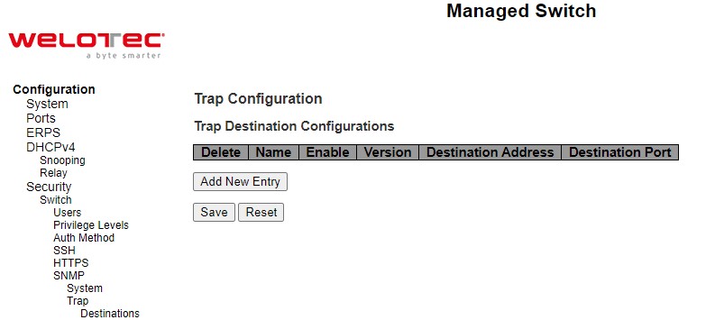
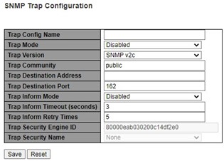
Table 2.22 Descriptions of SNMP Trap Destination Configurations
Label |
Description |
|---|---|
Mode |
Users are allowed to delete each entry separately. |
Name |
Indicates the trap Configuration’s name. Indicates the trap destination’s name. |
Enable |
Indicates the trap destination mode operation. Possible modes are: |
Version |
Indicates the SNMP trap supported version. Possible versions are: |
Destination Address |
Indicates the SNMP trap destination address. It allows a valid IPv4 address in dotted decimal notation (‘x.y.z.w’). It also allows a valid hostname. A valid hostname is a string drawn from the alphabet (AZa-z), digits (0-9), dot (.), dash (-). Spaces are not allowed, the first character must be an alpha character, and the first and last characters must not be a dot or a dash. |
Destination Port |
Indicates the SNMP trap destination port. SNMP Agent will send SNMP message via this port. The port range is 1~65535. |
SNMP Trap Sources
This page provides SNMP Trap Source configurations. A trap is sent for the given trap source if at least one filter with filter type included matches the filter, and no filters with filter type excluded matches. Figure 2.37 shows the webpage when there is no entry in the trap source configurations. When users click on the Add New Entry button, the webpage will be updated to Figure 2.38. The users can select Name for trap source from the drop-down list and select the type from the second drop-down list. Then, enter the Subset OID in the text field. Click on the Save button to save the changes or click on the Reset button to undo any changes made locally and revert to previously saved values. Table 2.23 provides descriptions of the SNMP Trap Source Configurations.
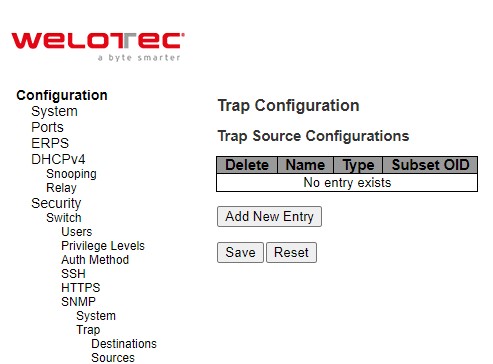
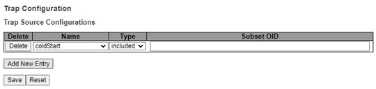
Table 2.23 Description of SNMP Trap Source Configurations:
Label |
Description |
|---|---|
Delete |
Check to delete the entry. It will be deleted during the next save. Users are allowed to delete each entry separately. |
Name |
Indicates the name for the entry. Selectable from the following list. |
Type |
The filter type for the entry. Possible types are: |
Subset OID |
The subset OID for the entry. The value should depend on the want kind of trap name. For example, the ifIdex is the subset OID of linkUp and linkDown. A valid subset OID is one or more digital number (0-4294967295) or asterisk () which are separated by dots (.). The first character must not begin with asterisk () and the maximum of OID count must not exceed 128. |
SNMP Communities
This submenu allows users to configure SNMP community table as shown in Figure 2.39. The entry index key is Community. This community string option allows the users to set a community string (Community name and Community secret) for authentication by adding new entry to the table. The users can remove existing community string from the list by clicking on the checkbox of Delete column at the beginning of each community string item**.** The users can specify the string names on the Community Name field by clicking Add New Entry button, as shown in Figure 2.40. Table 2.24 briefly provides descriptions of SNMP’s community setting.
Please click on the Save button afterwards for a change to take effect, or click Reset button to undo any changes made locally and revert to previously saved values.
Typically, an SNMP agent, which is a network management software module residing on the managed switch, can access all objects with read-all-only permissions using the string public. Another setting example is that the string private has permission of read-write-all.
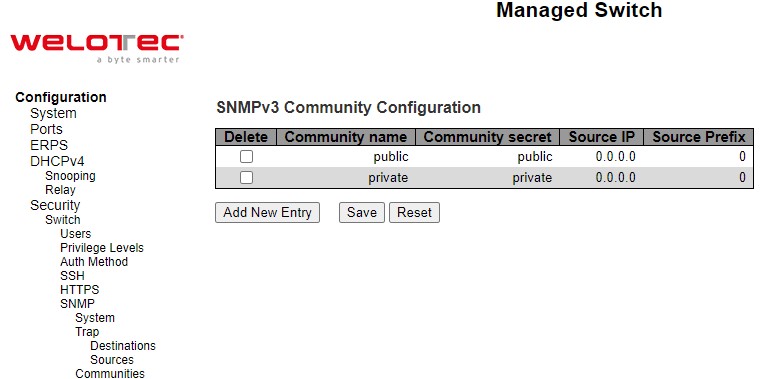
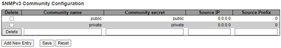
Table 2.24 Descriptions of SNMP Community Configurations:
Label |
Description |
|---|---|
Delete |
Check to delete the entry. It will be deleted during the next save. |
Community Name |
Indicates the community access string to permit access to SNMPv3 agent. The allowed string length is 1 to 32, and the allowed content is ASCII characters from 33 to 126. The community string will be treated as security name and map a SNMPv1 or SNMPv2c community string. |
Community Secret |
Indicates the community secret (access string) to permit access using SNMPv1 and SNMPv2c to the SNMP agent. The allowed string length is 1 to 32, and the allowed content is ASCII characters from 33 to 126. |
Source IP |
Indicates the SNMP access source address. A particular range of source addresses can be used to restrict source subnet when combined with source mask. |
Source Prefix |
Indicates the SNMP access source address mask. |
SNMP Users
This submenu allows users to configure SNMPv3 user table on this page. The entry index keys are Engine ID and User Name. As mentioned earlier, SNMPv3 is a more secure SNMP protocol than earlier versions. In this part, the users will be able to set a password and an encryption key to enhance the data security. When choosing this option, the users can configure SNMPv3’s authentication and encryption. MD5 (Message-Digest algorithm 5) is used for authentication password and DES (Data Encryption Standard) is used for data encryption algorithm. Figure 2.41 shows the SNMPv3 Authentication Setting’s options. The users can view existing SNMPv3 users’ setting on the upper table where it provides information about user name, authentication type, and data encryption (or privacy protocol). The users have an option to remove existing SNMPv3 user by clicking on the Delete button under the Delete column of each entry. To add a new SNMPv3 user, the users have to click Add New Entry button, and enter Engine ID, User Name, Security Level, Authentication Protocol, Authentication Password, Privacy Protocol, and Privacy Password. The authentication password has the maximum length of 31 characters. Note that if no password is provided, there will be no authentication for SNMPv3. Table 2.25 lists the descriptions of SNMPv3 User settings.
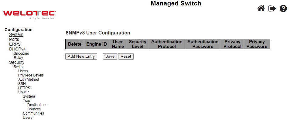
Table 2.25 Descriptions of SNMP Users:
Label |
Description |
Factory Default |
|---|---|---|
Delete |
Check to delete the entry. It will be deleted during the next save. |
|
Engine ID |
An octet string identifying the engine ID that this entry should belong to. The string must contain an even number (in hexadecimal format) with number of digits between 10 and 64, but all-zeros and all-‘F’s are not allowed. The SNMPv3 architecture uses the User-based Security Model (USM) for message security and the View-based Access Control Model (VACM) for access control. For the USM entry, the usmUserEngineID and usmUserName are the entry’s keys. In a simple agent, usmUserEngineID is always that agent’s own snmpEngineID value. The value can also take the value of the snmpEngineID of a remote SNMP engine with which this user can communicate. In other words, if user engine ID equal system engine ID then it is a local user; otherwise it is a remote user. |
Follow DUT’s MAC address to create Engine ID |
User Name |
A string identifying the user name that this entry should belong to. The allowed string length is 1 to 32, and the allowed content is ASCII characters from 33 to 126. |
|
Security Level |
Indicates the security model that this entry should belong to. Possible security models are: NoAuth, NoPriv: No authentication and no privacy. Auth, NoPriv: Authentication and no privacy. Auth, Priv: Authentication and privacy. The value of security level cannot be modified if entry already exists. That means it must first be ensured that the value is set correctly. |
Auth, Priv |
Authentication Protocol |
Indicates the authentication protocol that this entry should belong to. Possible authentication protocols are: None: No authentication protocol. MD5: An optional flag to indicate that this user uses MD5 authentication protocol. SHA: An optional flag to indicate that this user uses SHA authentication protocol. The value of security level cannot be modified if entry already exists. That means must first ensure that the value is set correctly. |
|
Authentification Password |
A string identifying the authentication password phrase. For MD5 authentication protocol, the allowed string length is 8 to 32. For SHA authentication protocol, the allowed string length is 8 to 40. The allowed content is ASCII characters from 33 to 126. |
Null |
Privacy Ptrotocol |
Indicates the privacy protocol that this entry should belong to. Possible privacy protocols are: None: No privacy protocol. DES: An optional flag to indicate that this user uses DES authentication protocol AES: NAn optional flag to indicate that this user uses AES authentication protocol |
DES |
Privacy Password |
A string identifying the privacy password phrase. The allowed string length is 8 to 32, and the allowed content is ASCII characters from 33 to 126. |
Null |
SNMP Groups
Figure 2.42 shows SNMPv3 Group Configuration webpage. It contains SNMPv3 group table. The entry index keys are Security Model and Security Name. Click Add New Entry button to add a new group entry to the table. Table 2.26 describes the column labels of the SNMPv3 group table.
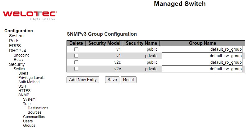
Table 2.26 Descriptions of SNMP Groups:
Label |
Description |
Factory Default |
|---|---|---|
Delete |
Check to delete the entry. It will be deleted during the next save. |
|
Security Model |
Indicates the security model that this entry should belong to. Possible security models are: v1: Reserverd for SNMPv1. v2c: Reserved for SNMPv2c. usm: SNMPv3, User-based Security Model (USM). |
v1 |
Security Name |
A string identifying the security name that this entry should belong to. The allowed string length is 1 to 32, and the allowed content is ASCII characters from 33 to 126. |
public |
Group Name |
A string identifying the security name that this entry should belong to. The allowed string length is 1 to 32, and the allowed content is ASCII characters from 33 to 126. |
Null |
SNMP Views
Figure 2.43 shows SNMPv3 View Configuration webpage. It contains SNMPv3 view table. The entry index keys are View Name and OID Subtree. Click Add New Entry button to add a new view entry to the table. Table 2.27 describes the column labels of the SNMPv3 view table. Please click on the Save button afterwards for a change to take effect, or click Reset button to undo any changes made locally and revert to previously saved values.
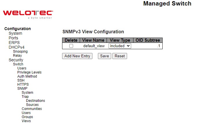
Table 2.27 Descriptions of SNMP Views:
Label |
Description |
Factory Default |
|---|---|---|
Delete |
Check to delete the entry. It will be deleted during the next save. |
|
View Name |
A string identifying the view name that this entry should belong to. The allowed string length is 1 to 32, and the allowed content is ASCII characters from 33 to 126. |
Null |
View Type |
Indicates the view type that this entry should belong to. Possible view types are: included: An optional flag to indicate that this view subtree should be included. excluded: An optional flag to indicate that this view subtree should be excluded. |
included |
OID Subtree |
The OID defining the root of the subtree to add to the named view. The allowed OID length is 1 to 128. The allowed string content is digital number or asterisk (*). |
Null |
SNMP Access
Figure 2.44 shows SNMPv3 Access Configuration webpage. It contains SNMPv3 access table. The entry index keys are Group Name, Security Model and Security Level. Click Add New Entry button to add a new access entry to the table. Table 2.28 describes the column labels of the SNMPv3 access table. Please click on the Save button afterwards for a change to take effect, or click Reset button to undo any changes made locally and revert to previously saved values.
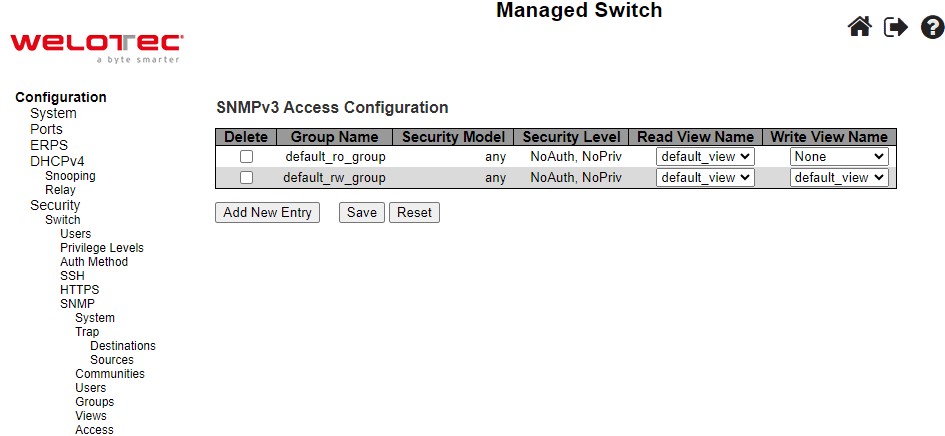
Table 2.28 Descriptions of SNMP Access Configuration:
Label |
Description |
Factory Default |
|---|---|---|
Delete |
Check to delete the entry. It will be deleted during the next save. |
|
Group Name |
A string identifying the group name that this entry should belong to. |
Default_ro_group |
Security Model |
Indicates the security model that this entry should belong to. Possible security models are: v1: Reserverd for SNMPv1. v2c: Reserved for SNMPv2c. usm: SNMPv3, User-based Security Model (USM). |
any |
Security Level |
Indicates the security model that this entry should belong to. Possible security models are: NoAuth, NoPriv: No authentication and no privacy. Auth,NoPriv: Authentication and no privacy. Auth, Priv: Authentication and privacy. |
NoAuth, NoPriv |
Read View Name |
The name of the MIB view defining the MIB objects for which this request may request the current values. |
None |
Group Name |
The name of the MIB view defining the MIB objects for which this request may potentially set the new values. |
None |
RMON Statistics
Figure 2.45 shows RMON (Remote Network Monitoring) Statistics Configuration. Welotec’s managed switch can monitoring network traffic on remote Ethernet segment to detect problem inside the network. The entry index key is ID for RMON Statistics table. Click Add New Entry button to add a new RMON Statistics entry to the table as shown in Figure 2.46. Table 2.29 describes the column labels of the RMON Statistics table. Please click on the Save button afterwards for a change to take effect, or click Reset button to undo any changes made locally and revert to previously saved values.
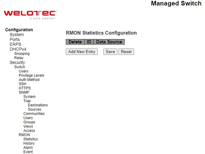
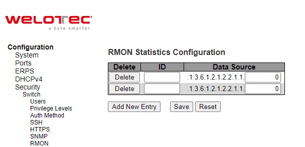
Table 2.29 Descriptions of RMON Statistics:
Label |
Description |
Factory Default |
|---|---|---|
Delete |
Check to delete the entry. It will be deleted during the next save. |
|
ID |
Indicates the index of the entry. The range is from 1 to 65535. |
Null |
Data Source |
Indicates the port ID which wants to be monitored. If in stacking switch, the value must add 1000000*(switch ID-1), for example, if the port is switch 3 port 5, the value is 2000005. |
.1.3.6.1.2.1.2.2.1.1.0 |
RMON History
Figure 2.47 shows RMON (Remote Network Monitoring) History Configuration. It displays RMON history table. The entry index key is ID for RMON history table. Click Add New Entry button to add a new RMON history entry to the table as shown in Figure 2.48. Table 2.30 describes the column labels of the RMON Statistics table. Please click on the Save button afterwards for a change to take effect, or click Reset button to undo any changes made locally and revert to previously saved values.
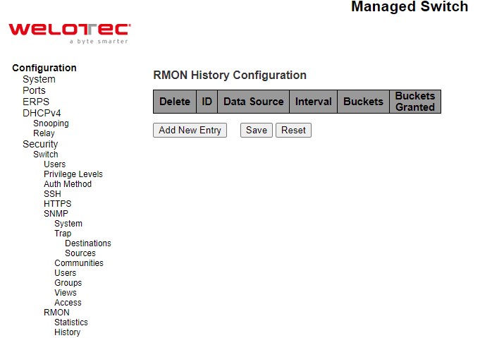
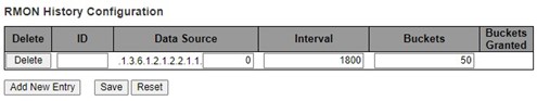
Table 2.30 Descriptions of RMON History:
Label |
Description |
Factory Default |
|---|---|---|
Delete |
Check to delete the entry. It will be deleted during the next save. |
|
ID |
Indicates the index of the entry. The range is from 1 to 65535. |
Null |
Data Source |
Indicates the port ID which wants to be monitored. If in stacking switch, the value must add 1000000*(switch ID-1), for example, if the port is switch 3 port 5, the value is 2000005. |
.1.3.6.1.2.1.2.2.1.1.0 |
Interval |
Indicates the interval in seconds for sampling the history statistics data. The range is from 1 to 3600, default value is 1800 seconds. |
1800 |
Buckets |
Indicates the maximum data entries associated this History control entry stored in RMON. The range is from 1 to 3600, default value is 50. |
50 |
Buckets Granted |
The number of data shall be saved in the RMON. |
RMON Alarm
Figure 2.49 shows RMON Alarm Configuration. It displays RMON alarm table. The entry index key is ID for RMON alarm table. Click Add New Entry button to add a new RMON alarm entry to the table as shown in Figure 2.49. Table 2.31 describes the column labels of the RMON alarm table. Please click on the Save button afterwards for a change to take effect, or click Reset button to undo any changes made locally and revert to previously saved values.
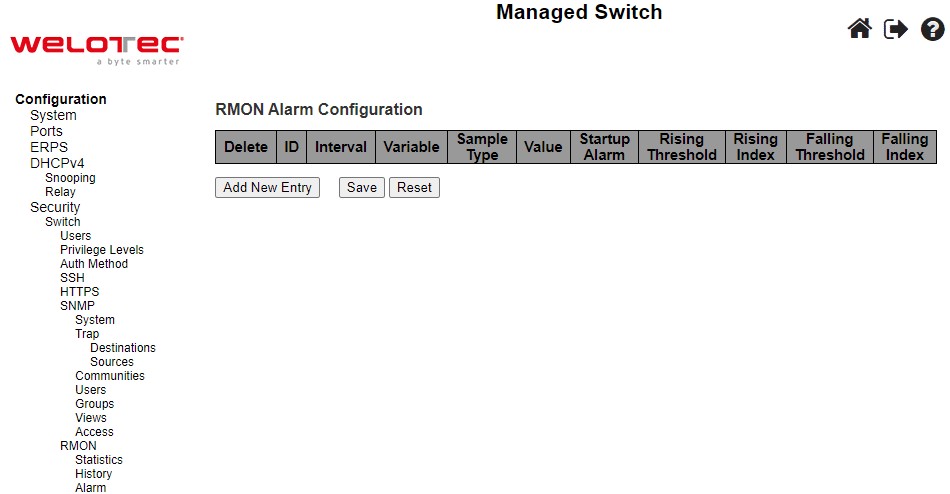
Table 2.31 Descriptions of RMON Alarm:
Label |
Description |
Factory Default |
|---|---|---|
Delete |
Check to delete the entry. It will be deleted during the next save. |
|
ID |
Indicates the index of the entry. The range is from 1 to 65535. |
Null |
Interval |
Indicates the interval in seconds for sampling the history statistics data. The range is from 1 to 3600, default value is 1800 seconds. |
30 |
Variable |
Indicates the port ID which wants to be monitored. If in stacking switch, the value must add 1000000*(switch ID-1), for example, if the port is switch 3 port 5, the value is 2000005. |
.1.3.6.1.2.1.2.2.1.0.0 |
Buckets |
Indicates the particular variable to be sampled, the possible variables are: InOctets: The total number of octets received on the interface, including framing characters. InUcastPkts: The number of uni-cast packets delivered to a higher-layer protocol. InNUcastPkts: The number of broad-cast and multi-cast packets delivered to a higher layer protocol. InDiscards: The number of inbound packets that are discarded even the packets are normal. InErrors: The number of inbound packets that contained errors preventing them from being deliverable to a higher-layer protocol. InUnknownProtos: The number of the inbound packets that were discarded because of the unknown or un-supported protocol. OutOctets: The number of octets transmitted out of the interface, including framing characters. OutUcastPkts: The number of uni-cast packets that request to transmit. OutNUcastPkts: The number of broad-cast and multi-cast packets that request to transmit. OutDiscards: The number of outbound packets that are discarded even the packets are normal. OutErrors: The number of outound packets that could not be transmitted because of errors. OutQLen: The length of the output packet queue (in packets). |
|
Sample Type |
The method of sampling the selected variable and calculating the value to be compared against the thresholds, possible sample types are: Absolute: Get the sample directly. Delta: Calculate the difference between samples (default). |
Delta |
Value |
The value of the statistic during the last sampling period. |
0 |
Start-up Alarm |
The method of sampling the selected variable and calculating the value to be compared against the thresholds, possible sample types are: Rising: Trigger alarm when the first value is larger than the rising threshold. Falling: Trigger alarm when the first value is less than the falling threshold. RisingOrFalling: Trigger alarm when the first value is larger than the rising threshold or less than the falling threshold (default). |
RisingOrFalling |
Rising Threshold |
Rising threshold value (-2147483648-2147483647). |
0 |
Rising Index |
Rising event index (0-65535). If this value is zero, no associated event will be generated, as zero is not a valid event index. |
0 |
Falling Threshold |
Falling threshold value (-2147483648-2147483647). |
0 |
Falling Index |
Falling event index (0-65535). If this value is zero, no associated event will be generated, as zero is not a valid event index. |
0 |
RMON Event
Figure 2.50 shows RMON Event Configuration. It displays RMON event table. The entry index key is ID for RMON event table. Click Add New Entry button to add a new RMON event entry to the table as shown in Figure 2.50. Table 2.32 describes the column labels of the RMON alarm table. Please click on the Save button afterwards for a change to take effect, or click Reset button to undo any changes made locally and revert to previously saved values.
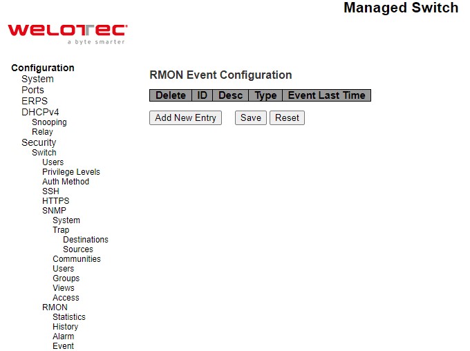
Table 2.32 Descriptions of RMON Event:
Label |
Description |
Factory Default |
|---|---|---|
Delete |
Check to delete the entry. It will be deleted during the next save. |
|
ID |
Indicates the index of the entry. The range is from 1 to 65535. |
Null |
Desc |
Indicates this event, the string length is from 0 to 127, default is a null string. |
Null |
Type |
Indicates the notification of the event, the possible types are: none: No SNMP log is created, no SNMP trap is sent. log: Create SNMP log entry when event is triggered. snmptrap: Send SNMP trap when the event is triggered. logandtrap: Create SNMP log entry and sent SNMP trap when the event is triggered. |
None |
Event Last Time |
Indicates the value of sysUpTime at the time this event entry last generated an event. |
0 |
Network
Under this Security⭢Network submenus, the users can configure network security for the RSAES managed switch. Figure 2.51 shows list of menus under the Security⭢Network. Under this section, the users can setup security for port, network access server (NAS), access control list (ACL), IP source guard, and ARP (Address Resolution Protocol) inspection.
Port Security Configuration
Global and per-port security of the managed switch can be configured in this webpage as shown in Figure 2.52. Port Security allows for limiting the number of users on a given port. A user is identified by a MAC address and VLAN ID. If Port Security is enabled on a port, the limit specifies the maximum number of users on the port. If this number is exceeded, an action is taken depending on violation mode. The violation mode can be one of the four different described below. The Port Security Configuration on this page consists of two sections: Global Configuration and Port Configuration. Table 2.33 summarizes the description of options for global and per-port configuration settings.
Please click on the Save button afterwards for a change to take effect, or click Reset button to undo any changes made locally and revert to previously saved values.
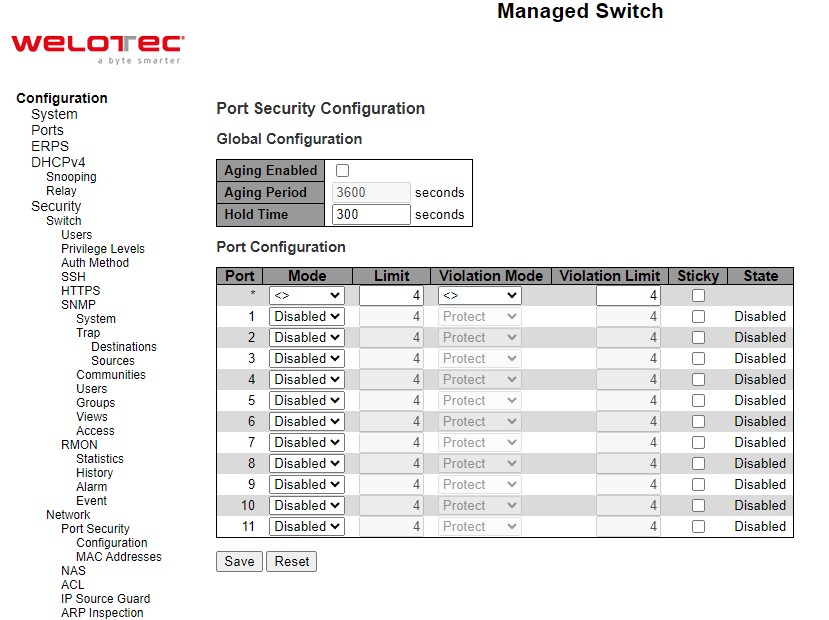
Table 2.33 Descriptions of Port Security Configuration:
Label |
Description |
Factory Default |
|---|---|---|
Port |
The port number to which the configuration below applies. |
Port no. 1 ~ 11 |
Mode |
Controls whether Port Security is enabled on this port. Notice that other modules may still use the underlying port security features without enabling Port Security on a given port. |
Disabled |
Limit |
The maximum number of MAC addresses that can be secured on this port. This number cannot exceed 1023. Default is 4. If the limit is exceeded, an action is taken corresponding to the violation mode. The switch is “born” with a total number of MAC addresses from which all ports draw whenever a new MAC address is seen on a Port Security-enabled port. Since all ports draw from the same pool, it may happen that a configured maximum cannot be granted, if the remaining ports have already used all available MAC addresses. |
4 |
Violation Mode |
If Limit is reached, the switch can take one of the following actions: Protect: Do not allow more than Limit MAC addresses on the port, but take no further action. Restrict: If Limit is reached, subsequent MAC addresses on the port will be counted and marked as violating. Such MAC addresses are removed from the MAC table when the hold time expires. At most Violation Limit MAC addresses can be marked as violating at any given time. Shutdown: If Limit is reached, one additional MAC address will cause the port to be shut down. This implies that all secured MAC addresses be removed from the port, and no new addresses be learned. There are three ways to re-open the port: 1) In the “Configuration⭢Ports” page’s “Configured” column, first disable the port, then restore the original mode. 2) Make a Port Security configuration change on the port. 3) Boot the switch. |
Protect |
Violation Limit |
The maximum number of MAC addresses that can be marked as violating on this port. This number cannot exceed 1023. Default is 4. It is only used when Violation Mode is Restrict. |
4 |
Sticky |
Enables sticky learning of MAC addresses on this port. When the port is in sticky mode, all MAC addresses that would otherwise have been learned as dynamic are learned as sticky. Sticky MAC addresses are part of the running-config and can therefore be saved to start-up-config. Sticky MAC addresses survive link changes (in contrast to Dynamic, which will have to be learned again). They also survive reboots if running-config is saved to startup-config. A port can be Sticky-enabled whether or not Port Security is enabled on that interface. In that way, it is possible to add sticky MAC addresses managementwise before enabling Port Security. To do that, use the “Configuration⭢Security⭢Port Security⭢MAC Addresses” page |
Unclicked |
State |
This column shows the current Port Security state of the port. The state takes one of four values: Disabled: Port Security is disabled at the port. Ready: The limit is not reached. This can be shown for all violation modes. Disabled: Indicates that the limit is reached on this port. This can be shown for all violation modes. Shutdown: Indicates that the port is shut down by Port Security. This state can only be shown if violation mode is set to Shutdown. |
Disabled |
Port Security MAC Addresses
In this webpage as shown in Figure 2.53, the users may add and delete static and sticky MAC addresses managed by Port Security. The port security defines three types of MAC addresses, of which static and sticky can be added and removed on this page:
Static: A MAC address added by end-user through management. Static MAC addresses are not subject to aging and will be added to the MAC address table once Port Security gets enabled on the interface. Static entries are part of the running-config and will survive interface link state changes and reboots if saved to startupconfig. Static entries can be added to the running-config at any time whether or not Port Security is enabled.
Sticky: When the interface is in sticky mode, all entries that would otherwise have been learned as dynamic are learned as sticky. Like static entries, sticky entries are part of the running-config and will survive interface link state changes and reboots if saved to the startup-config. Though not the intention with Sticky entries, they can be added by management to the running-config at any time whether or not Port Security is enabled on the interface, as long as the interface is in Sticky mode. Sticky entries will disappear if the interface is taken out of Sticky mode.
To add a new entry to the table of Port Security Static and Sticky MAC Addresses, click on Add New MAC Entry button. The new entry as shown in Figure 2.53 allows for adding static or sticky MAC address to a particular interface. When adding is finished, click the Save button to save the changes to running-config. Notice that sticky entries are normally added automatically through learning on the interface. Table 2.34 provides descriptions of the fields for Port Security Static and Sticky MAC Addresses.
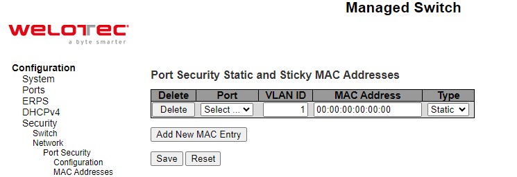
Table 2.34 Descriptions of RMON Event:
Label |
Description |
Factory Default |
|
|---|---|---|---|
Delete |
Press this button to remove the entry from the MAC address table (if present) and the running-config. Notice that dynamic entries may be removed all-together on an interface through “Monitor->Security->Port Security->Switch” and one-by-one through “Monitor->Security->Port Security->Port” |
||
Port |
The port number to which this MAC address is bound. |
Select… |
|
VLAN ID |
The VLAN ID in question. |
1 |
|
MAC Address |
The MAC address in question. |
00:00:00:00:00:00 |
|
Type |
Indicates the type of entry and may be either Static or Sticky (see description above). |
Static |
NAS
NAS is an acronym for Network Access Server. The NAS is meant to act as a gateway to guard access to a protected source. A client connects to the NAS, and the NAS connects to another resource asking whether the client’s supplied credentials are valid. Based on the answer, the NAS then allows or disallows access to the protected resource. An example of a NAS implementation is IEEE 802.1X.
The IEEE 802.1X standard defines a port-based access control procedure that prevents unauthorized access to a network by requiring users to first submit credentials for authentication. One or more central servers, the backend servers, determine whether the user is allowed access to the network. These backend (RADIUS) servers are configured on the “Configuration⭢Security⭢AAA” webpage. The IEEE802.1X standard defines port-based operation, but non-standard variants overcome security limitations.
MAC-based authentication allows for authentication of more than one user on the same port, and doesn’t require the user to have special 802.1X supplicant software installed on his/her system. The switch uses the user’s MAC address to authenticate against the backend server. Intruders can create counterfeit MAC addresses, which makes MAC-based authentication less secure than 802.1X authentication.
This feature provides access control on a port basis. There are two types of authentications: IEEE 802.1X and MAC-based. The 802.1X supports Port-based 802.1X authentication type. The following three terms are used in the 802.1X context: Supplicant, Authenticator, and the Authentication server. The Supplicant is the client (PC) with some 801.1X software, where the Authenticator is the switch, and the Authentication server is such as a RADIUS server. The supplicant/client is connected to the authenticator/switch on some port, and the authenticator can reach an authentication server. The idea is that the supplicant wants access to the port, so it sends an Extensible Authentication Protocol over LAN (EAPoL) message to the authenticator, which in turn asks the authenticator server if this supplicant can be accepted. Then the authenticator opens the port for the supplicant, and communication can begin. Depending on how the authenticator is configured, this process bRSAESaves in different ways.
In Port-based 802.1X, if the supplicant S is on network N (connected to the authenticator on Port A) and S opens Port A, then everyone on network N will have access. However, only the supplicant that opened the port on the authenticator is allowed to transmit and receive packets. This is done through the MAC address of the supplicant.
A supplicant can be seen as a combination of a client and a supplicant component (that takes care of negotiating the port opening when the client transmits the first packet). This embedded supplicant component then uses the MAC address of the client as the username and password in the form aa-bb-cc-dd-ee-ff. This has the advantage that the client does not need to have supplicant software.
The Configuration -> Security -> Network -> NAS (Network Access Server) webpage as shown in Figure 2.54 allows the user to configure the IEEE 802.1X and MAC-based authentication system and port settings. The NAS configuration consists of two sections: a system- (System Configuration) and a port-wide (Port Configuration). Table 2.35 provides detailed descriptions of options for both System Configuration and Port Configuration.
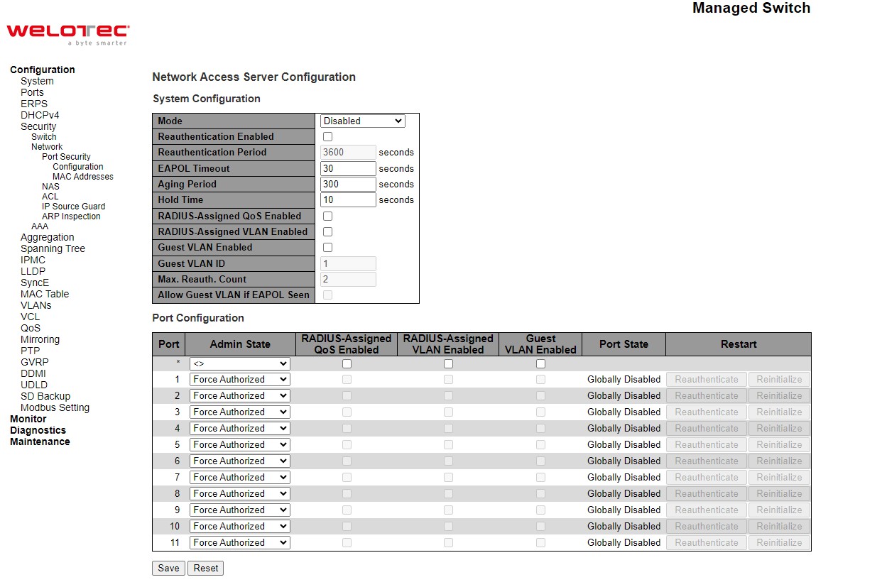
Table 2.35 Descriptions of Network NAS:
C |
Description |
Factory Default |
|---|---|---|
System Configuration |
||
Mode |
Indicates if NAS is globally enabled or disabled on the switch. If globally disabled, all ports are allowed forwarding of frames. |
Disabled |
Reauthentication Enabled |
If checked, successfully authenticated supplicants/clients are reauthenticated after the interval specified by the Reauthentication Period. Reauthentication for 802.1X-enabled ports can be used to detect if a new |
Unclicked |
Label |
Description |
Factory Default |
|---|---|---|
device is plugged into a switch port or if a supplicant is no longer attached. For MAC-based ports, reauthentication is only useful if the RADIUS server configuration has changed. It does not involve communication between the switch and the client, and therefore doesn’t imply that a client is still present on a port (see Aging Period below). |
||
Reauthentication Period |
Determines the period, in seconds, after which a connected client must be reauthenticated. This is only active if the Reauthentication Enabled checkbox is checked. Valid values are in the range 1 to 3600 seconds. |
3600 |
EAPOL Timeout |
Determines the time for retransmission of Request Identity EAPOL frames. Valid values are in the range 1 to 65535 seconds. This has no effect for MAC-based ports. |
30 |
Aging Period |
This setting applies to the following modes, i.e. modes using the Port Security functionality to secure MAC addresses: • MAC-Based Auth. When the NAS module uses the Port Security module to secure MAC addresses, the Port Security module needs to check for activity on the MAC address in question at regular intervals and free resources if no activity is seen within a given period of time. This parameter controls exactly this period and can be set to a number between 10 and 1000000 seconds. If reauthentication is enabled and the port is in an 802.1X-based mode, this is not so critical, since supplicants that are no longer attached to the port will get removed upon the next reauthentication, which will fail. But if reauthentication is not enabled, the only way to free resources is by aging the entries. For ports in MAC-based Auth. mode, reauthentication doesn’t cause direct communication between the switch and the client, so this will not detect whether the client is still attached or not, and the only way to free any resources is to age the entry. |
300 |
Hold Time |
This setting applies to the following modes, i.e. modes using the Port Security functionality to secure MAC addresses: • MAC-Based Auth. If a client is denied access - either because the RADIUS server denies the client access or because the RADIUS server request times out (according to the timeout specified on the “Configuration→Security→AAA” page) - the client is put on hold in the Unauthorized state. The hold timer does not count during an on-going authentication. In MAC-based Auth. mode, the switch will ignore new frames coming from the client during the hold time. The Hold Time can be set to a number between 10 and 1000000 seconds. |
10 |
RADIUS-Assigned QoS Enabled |
RADIUS-assigned QoS provides a means to centrally control the traffic class to which traffic coming from a successfully authenticated supplicant is assigned on the switch. The RADIUS server must be configured to transmit special RADIUS attributes to take advantage of this feature (see RADIUS-Assigned QoS Enabled below for a detailed description). The “RADIUS-Assigned QoS Enabled” checkbox provides a quick way to globally enable/disable RADIUS-server assigned QoS Class functionality. When checked, the individual ports’ ditto setting determines whether RADIUS-assigned QoS Class is enabled on that port. When unchecked, RADIUS-server assigned QoS Class is disabled on all ports. |
Unclicked |
RADIUS-Assigned VLAN Enabled |
RADIUS-assigned VLAN provides a means to centrally control the VLAN on which a successfully authenticated supplicant is placed on the switch. Incoming traffic will be classified to and switched on the RADIUSassigned VLAN. The RADIUS server must be configured to transmit special RADIUS attributes to take advantage of this feature (see RADIUSAssigned VLAN Enabled below for a detailed description). |
Unclicked |
Label |
Description |
Factory Default |
|---|---|---|
The “RADIUS-Assigned VLAN Enabled” checkbox provides a quick way to globally enable/disable RADIUS-server assigned VLAN functionality. When checked, the individual ports’ ditto setting determines whether RADIUS-assigned VLAN is enabled on that port. When unchecked, RADIUS-server assigned VLAN is disabled on all ports. |
||
Guest VLAN Enabled |
A Guest VLAN is a special VLAN - typically with limited network access - on which 802.1X-unaware clients are placed after a network administrator-defined timeout. The switch follows a set of rules for entering and leaving the Guest VLAN as listed below. The “Guest VLAN Enabled” checkbox provides a quick way to globally enable/disable Guest VLAN functionality. When checked, the individual ports’ ditto setting determines whether the port can be moved into Guest VLAN. When unchecked, the ability to move to the Guest VLAN is disabled on all ports. |
Unclicked |
Guest VLAN ID |
This is the value that a port’s Port VLAN ID is set to if a port is moved into the Guest VLAN. It is only changeable if the Guest VLAN option is globally enabled. Valid values are in the range [1; 4095]. |
1 |
Max. Reauth. Count |
The number of times the switch transmits an EAPOL Request Identity frame without response before considering entering the Guest VLAN is adjusted with this setting. The value can only be changed if the Guest VLAN option is globally enabled. Valid values are in the range [1; 255]. |
2 |
Allow Guest VLAN if EAPOL Seen |
The switch remembers if an EAPOL frame has been received on the port for the life-time of the port. Once the switch considers whether to enter the Guest VLAN, it will first check if this option is enabled or disabled. If disabled (unchecked; default), the switch will only enter the Guest VLAN if an EAPOL frame has not been received on the port for the life-time of the port. If enabled (checked), the switch will consider entering the Guest VLAN even if an EAPOL frame has been received on the port for the lifetime of the port. The value can only be changed if the Guest VLAN option is globally enabled. |
Unclicked |
Port Configuration |
||
Port |
The port number for which the configuration below applies. |
|
Admin State |
If NAS is globally enabled, this selection controls the port’s authentication mode. The following modes are available: Force Authorized In this mode, the switch will send one EAPOL Success frame when the port link comes up, and any client on the port will be allowed network access without authentication. Force Unauthorized In this mode, the switch will send one EAPOL Failure frame when the port link comes up, and any client on the port will be disallowed network access. Port-based 802.1X In the 802.1X-world, the user is called the supplicant, the switch is the authenticator, and the RADIUS server is the authentication server. The authenticator acts as the man-in-the-middle, forwarding requests and responses between the supplicant and the authentication server. Frames sent between the supplicant and the switch are special 802.1X frames, known as EAPOL (EAP Over LANs) frames. EAPOL frames encapsulate EAP PDUs (RFC3748). Frames sent between the switch and the RADIUS server are RADIUS packets. RADIUS packets also encapsulate EAP PDUs together with other attributes like the switch’s IP address, name, and the supplicant’s port number on the switch. EAP is very flexible, in that it allows for different authentication methods, like MD5-Challenge, PEAP, |
Force Authorized |
Label |
Description |
Factory Default |
|---|---|---|
and TLS. The important thing is that the authenticator (the switch) doesn’t need to know which authentication method the supplicant and the authentication server are using, or how many information exchange frames are needed for a particular method. The switch simply encapsulates the EAP part of the frame into the relevant type (EAPOL or RADIUS) and forwards it. When authentication is complete, the RADIUS server sends a special packet containing a success or failure indication. Besides forwarding this decision to the supplicant, the switch uses it to open up or block traffic on the switch port connected to the supplicant. Note: Suppose two backend servers are enabled and that the server timeout is configured to X seconds (using the AAA configuration page), and suppose that the first server in the list is currently down (but not considered dead). Now, if the supplicant retransmits EAPOL Start frames at a rate faster than X seconds, then it will never get authenticated, because the switch will cancel on-going backend authentication server requests whenever it receives a new EAPOL Start frame from the supplicant. And since the server hasn’t yet failed (because the X seconds haven’t expired), the same server will be contacted upon the next backend authentication server request from the switch. This scenario will loop forever. Therefore, the server timeout should be smaller than the supplicant’s EAPOL Start frame retransmission rate. MAC-based Auth. Unlike port-based 802.1X, MAC-based authentication is not a standard, but merely a best-practices method adopted by the industry. In MACbased authentication, users are called clients, and the switch acts as the supplicant on bRSAESalf of clients. The initial frame (any kind of frame) sent by a client is snooped by the switch, which in turn uses the client’s MAC address as both username and password in the subsequent EAP exchange with the RADIUS server. The 6-byte MAC address is converted to a string on the following form “xx-xx-xx-xx-xx-xx”, that is, a dash (-) is used as separator between the lower-cased hexadecimal digits. The switch only supports the MD5-Challenge authentication method, so the RADIUS server must be configured accordingly. When authentication is complete, the RADIUS server sends a success or failure indication, which in turn causes the switch to open up or block traffic for that particular client, using the Port Security module. Only then will frames from the client be forwarded on the switch. There are no EAPOL frames involved in this authentication, and therefore, MAC-based Authentication has nothing to do with the 802.1X standard. The advantage of MAC-based authentication over 802.1X-based authentication is that the clients don’t need special supplicant software to authenticate. The disadvantage is that MAC addresses can be spoofed by malicious users - equipment whose MAC address is a valid RADIUS user can be used by anyone. Also, only the MD5-Challenge method is supported. The maximum number of clients that can be attached to a port can be limited using the Port Security Limit Control functionality. |
||
RADIUS-Assigned QoS Enabled |
When RADIUS-Assigned QoS is both globally enabled and enabled (checked) on a given port, the switch reacts to QoS Class information carried in the RADIUS Access-Accept packet transmitted by the RADIUS server when a supplicant is successfully authenticated. If present and valid, traffic received on the supplicant’s port will be classified to the given QoS Class. If (re-)authentication fails or the RADIUS Access-Accept packet no longer carries a QoS Class or it’s invalid, or the supplicant is otherwise no longer present on the port, the port’s QoS Class is immediately reverted to the original QoS Class (which may be changed by the administrator in the meanwhile without affecting the RADIUS-assigned). |
Unclicked |
Label |
Description |
Factory Default |
|---|---|---|
This option is only available for single-client modes, i.e. Port-based 802.1X Single 802.1X RADIUS attributes used in identifying a QoS Class: The User-Priority-Table attribute defined in RFC4675 forms the basis for identifying the QoS Class in an Access-Accept packet. Only the first occurrence of the attribute in the packet will be considered, and to be valid, it must follow this rule: All 8 octets in the attribute’s value must be identical and consist of ASCII characters in the range ‘0’ - ‘7’, which translates into the desired QoS Class in the range [0; 7]. |
||
RADIUS-Assigned VLAN Enabled |
When RADIUS-Assigned VLAN is both globally enabled and enabled (checked) for a given port, the switch reacts to VLAN ID information carried in the RADIUS Access-Accept packet transmitted by the RADIUS server when a supplicant is successfully authenticated. If present and valid, the port’s Port VLAN ID will be changed to this VLAN ID, the port will be set to be a member of that VLAN ID, and the port will be forced into VLAN unaware mode. Once assigned, all traffic arriving on the port will be classified and switched on the RADIUS-assigned VLAN ID. If (re-)authentication fails or the RADIUS Access-Accept packet no longer carries a VLAN ID or it’s invalid, or the supplicant is otherwise no longer present on the port, the port’s VLAN ID is immediately reverted to the original VLAN ID (which may be changed by the administrator in the meanwhile without affecting the RADIUS-assigned). This option is only available for single-client modes, i.e. Port-based 802.1X Single 802.1X For trouble-shooting VLAN assignments, use the “Monitor->VLANs->VLAN Membership and VLAN Port” pages. These pages show which modules have (temporarily) overridden the current Port VLAN configuration. RADIUS attributes used in identifying a VLAN ID: RFC2868 and RFC3580 form the basis for the attributes used in identifying a VLAN ID in an Access-Accept packet. The following criteria are used: The Tunnel-Medium-Type, Tunnel-Type, and Tunnel-Private-Group- ID attributes must all be present at least once in the Access-Accept packet. The switch looks for the first set of these attributes that have the same Tag value and fulfil the following requirements (if Tag == 0 is used, the Tunnel-Private-Group-ID does not need to include a Tag): Value of Tunnel-Medium-Type must be set to “IEEE-802” (ordinal 6). Value of Tunnel-Type must be set to “VLAN” (ordinal 13). Value of Tunnel-Private-Group-ID must be a string of ASCII chars in the range ‘0’ - ‘9’, which is interpreted as a decimal string representing the VLAN ID. Leading ‘0’s are discarded. The final value must be in the range [1; 4095]. |
Unclicked |
Guest VLAN Enabled |
When Guest VLAN is both globally enabled and enabled (checked) for a given port, the switch considers moving the port into the Guest VLAN according to the rules outlined below. This option is only available for EAPOL-based modes, i.e.: Port-based 802.1X Single 802.1X Multi 802.1X For trouble-shooting VLAN assignments, use the “Monitor→VLANs→VLAN Membership and VLAN Port” pages. These pages show which modules have (temporarily) overridden the current Port |
Unclicked |
Label |
Description |
Factory Default |
VLAN configuration. Guest VLAN Operation: When a Guest VLAN enabled port’s link comes up, the switch starts transmitting EAPOL Request Identity frames. If the number of transmissions of such frames exceeds Max. Reauth. Count and no EAPOL frames have been received in the meanwhile, the switch considers entering the Guest VLAN. The interval between transmission of EAPOL Request Identity frames is configured with EAPOL Timeout. If Allow Guest VLAN if EAPOL Seen is enabled, the port will now be placed in the Guest VLAN. If disabled, the switch will first check its history to see if an EAPOL frame has previously been received on the port (this history is cleared if the port link goes down or the port’s Admin State is changed), and if not, the port will be placed in the Guest VLAN. Otherwise it will not move to the Guest VLAN, but continue transmitting EAPOL Request Identity frames at the rate given by EAPOL Timeout. Once in the Guest VLAN, the port is considered authenticated, and all attached clients on the port are allowed access on this VLAN. The switch will not transmit an EAPOL Success frame when entering the Guest VLAN. While in the Guest VLAN, the switch monitors the link for EAPOL frames, and if one such frame is received, the switch immediately takes the port out of the Guest VLAN and starts authenticating the supplicant according to the port mode. If an EAPOL frame is received, the port will never be able to go back into the Guest VLAN if the “Allow Guest VLAN if EAPOL Seen” is disabled. |
||
Port Status |
The current state of the port. It can undertake one of the following values: Globally Disabled: NAS is globally disabled. Link Down: NAS is globally enabled, but there is no link on the port. Authorized: The port is in Force Authorized or a single-supplicant mode and the supplicant is authorized. Unauthorized: The port is in Force Unauthorized or a single-supplicant mode and the supplicant is not successfully authorized by the RADIUS server. X Auth/Y Unauth: The port is in a multi-supplicant mode. Currently X clients are authorized and Y are unauthorized. |
Globally Disabled |
Restart |
Two buttons are available for each row. The buttons are only enabled when authentication is globally enabled and the port’s Admin State is in an EAPOL-based mode. Clicking these buttons will not cause settings changed on the page to take effect. Reauthenticate: Schedules a reauthentication whenever the quiet-period of the port runs out (EAPOL-based authentication). The button only has effect for successfully authenticated clients on the port and will not cause the clients to get temporarily unauthorized. Reinitialize: Forces a reinitialization of the clients on the port and thereby a reauthentication immediately. The clients will transfer to the unauthorized state while the reauthentication is in progress. |
- |
Click Refresh button to refresh the page. Click Save button to save changes. Click Reset button to undo any changes made locally and revert to previously saved values.
ACL
ACL is an acronym for Access Control List. It is the list table of ACEs, containing Access Control Entries that specify individual users or groups permitted or denied to specific traffic objects, such as a process or a program. Each accessible traffic object contains an identifier to its ACL. The privileges determine whether there are specific traffic object access rights. ACL implementations can be quite complex, for example, when the ACEs are prioritized for the various situation. In networking, the ACL refers to a list of service ports or network services that are available on a host or server, each with a list of hosts or servers permitted or denied to use the service. ACL can generally be configured to control inbound traffic, and in this context, they are similar to firewalls. There are 3 web-pages associated with the manual ACL configuration: ACL Ports, ACL Rate Limiters, and ACL Access Control List. Figure 2.55 shows the list of ACL menus. The following subsections will describe each ACL configuration.
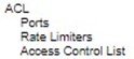
ACL Ports
The ACL⭢Ports webpage is depicted in Figure 2.56. The ACL Ports configuration is used to assign a Policy ID to an ingress port. This is useful to group ports to obey the same traffic rules. Traffic Policy is created under the “Access Control List” - page. You can also set up specific traffic properties (Action / Rate Limiter / Port copy, etc) for each ingress port. They will though only apply if the frame gets past the ACE (Access Control Entry) matching without getting matched. In that case a counter associated with that port is incremented. Table 2.36 summarizes description for each specific port property.
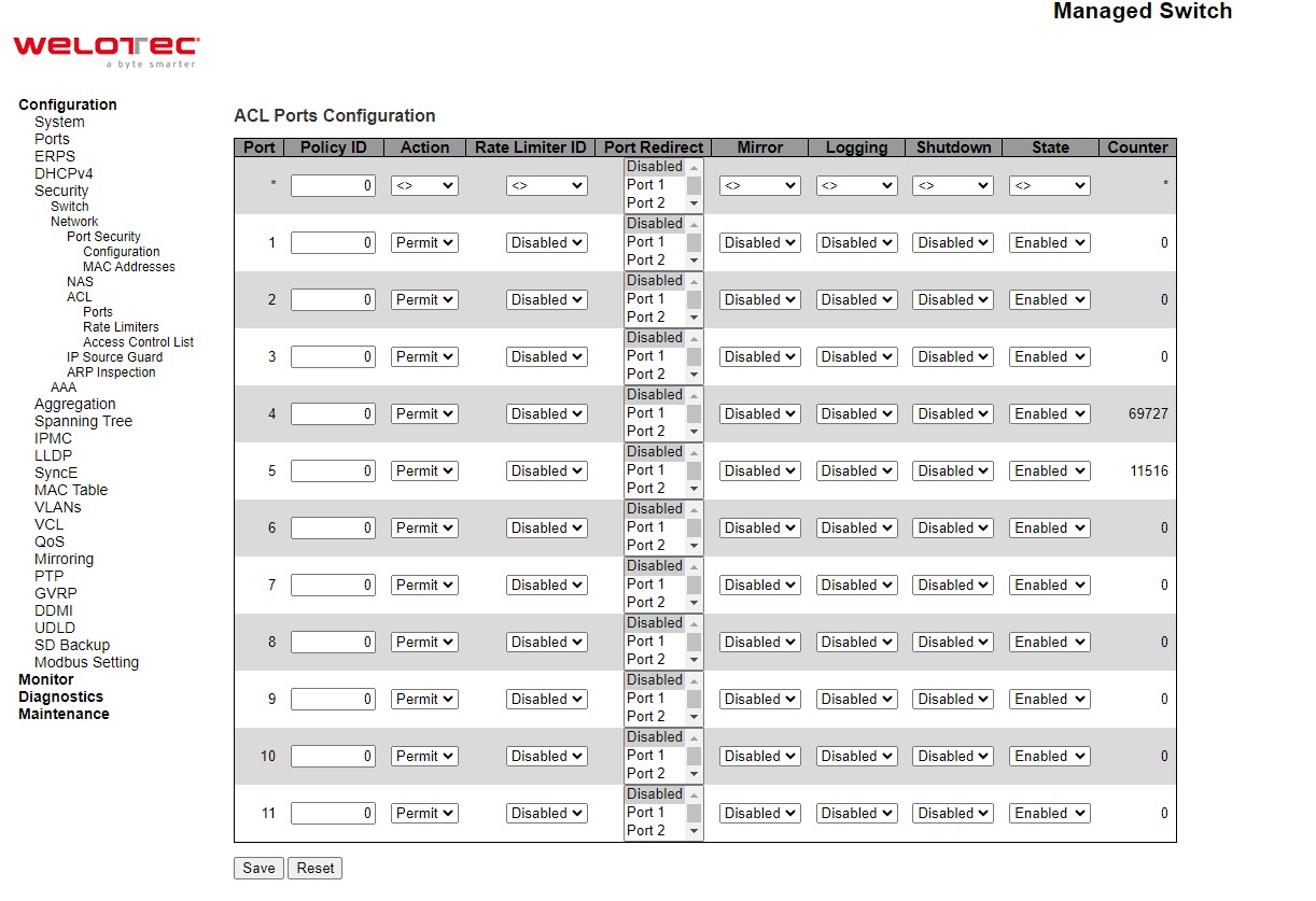
Table 2.36 Descriptions of Network ACL Ports:
Label |
Description |
Factory Default |
|---|---|---|
Port |
The logical port for the settings contained in the same row. |
Port ID from 1 to 11 |
Policy ID |
Select the policy to apply to this port. The allowed values are 0 through 255. The default value is 0. |
0 |
Action |
Select whether forwarding is permitted (“Permit”) or denied (“Deny”). The default value is “Permit”. |
Permit |
Rate Limiter ID |
Select which rate limiter to apply on this port. The allowed values are Disabled or the values 1 through 16. The default value is “Disabled”. |
Disabled |
Port Redirect |
Select which port frames are redirected on. The allowed values are Disabled or a specific port number and it can’t be set when action is permitted. The default value is “Disabled”. |
Disabled |
Mirror |
Specify the mirror operation of this port. The allowed values are: Enabled: Frames received on the port are mirrored. Disabled: Frames received on the port are not mirrored. The default value is “Disabled”. |
Disabled |
Logging |
Specify the logging operation of this port. Notice that the logging message doesn’t include the 4 bytes CRC. The allowed values are: Enabled: Frames received on the port are stored in the System Log. Disabled: Frames received on the port are not logged. The default value is “Disabled”. Note: The logging feature only works when the packet length is less than 1518 (without VLAN tags) and the System Log memory size and logging rate is limited. |
Disabled |
Shutdown |
Specify the port shut down operation of this port. The allowed values are: Enabled: If a frame is received on the port, the port will be disabled. Disabled:Port shut down is disabled. The default value is “Disabled”. Note: The shutdown feature only works when the packet length is less than 1518(without VLAN tags). |
Disabled |
State |
Specify the port state of this port. The allowed values are: Enabled: To reopenports by changing the volatile port configuration of the ACL user module. Disabled: To close ports by changing the volatile port configuration of the ACL user module. The default value is “Enabled”. |
Disabled |
Counter |
Counts the number of frames that match this ACE. |
0 |
Click Save button to save changes. Click Reset button to undo any changes made locally and revert to previously saved values.
ACL Rate Limiters
The ACL⭢Rate Limiters webpage is shown in Figure 2.57. Under this page, the users can configure the rate limiters. There can be 15 different rate limiters, each ranging from 1-1024K packets per seconds. Under “Ports” and “Access Control List” web-pages you can assign a Rate Limiter ID to the ACE(s) or ingress port(s). Table 2.37 describes the labels of ACL Rate Limiters Configuration.
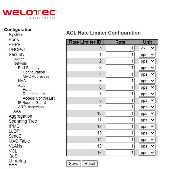
Table 2.37 Descriptions of Network ACL Rate Limiters:
Label |
Description |
Factory Default |
|---|---|---|
Rate Limiter ID |
The rate limiter ID for the settings contained in the same row and its range is 1 to 16. |
Limiter ID 1 to 16 |
Rate |
The valid rate is 0 - 99, 100, 200, 300, …, 1092000 in pps or 0, 100, 200, 300, …, 1000000 in kbps |
1 |
Unit |
Specify the rate unit. The allowed values are: pps: packets per second. kbps: Kbits per second |
pps |
Click Save button to save changes. Click Reset button to undo any changes made locally and revert to previously saved values.
ACL Access Control List
The ACL -> Access Control List webpage shows the ACEs in a prioritized way, highest (top) to lowest (bottom). By default, the table is empty as shown in Figure 2.58. When click on the plus sign icon at the end of the table, a set of parameters are listed as three tables under the ACE Configuration webpage as shown in Figure 2.59.
In Figure 2.58, users can select auto-refresh option by checking the Auto-refresh box to refresh the page automatically. Automatic refresh occurs every 3 seconds. Users can click Refresh button to refresh the page; any changes made locally will be undone. Users can click Clear button to clear the counters. Lastly, users can click Remove All button to remove all ACEs.
An ingress frame will only get a hit on one ACE even though there are more matching ACEs. The first matching ACE will act (permit/deny) on that frame and a counter associated with that ACE is incremented. An ACE can be associated with a Policy, 1 ingress port, or any ingress port (the whole switch). If an ACE Policy is created then that Policy can be associated with a group of ports under the “Ports” web-page. There are number of parameters that can be configured with an ACE. Table 2.38 provides additional information for each parameter to configure the ACL. The maximum number of ACEs is 64.
Table 2.38 Summary of Label, Description, and Factory Default for ACL (Access Control List):
Label |
Description |
Factory Default |
|---|---|---|
ACE Configuration |
||
ACE |
Indicates the ACE ID. |
Disabled |
Ingress Port |
Indicates the ingress port of the ACE. Possible values are: All: The ACE will match all ingress port. Port: The ACE will match a specific ingress port. |
All |
Policy/Bitmask |
Indicates the policy number and bitmask of the ACE. |
Any |
Frame Type |
Indicates the frame type of the ACE. Possible values are: Any: The ACE will match any frame type. EType: The ACE will match Ethernet Type frames. Note that an Ethernet Type based ACE will not get matched by IP and ARP frames. ARP: The ACE will match ARP/RARP frames. IPv4: The ACE will match all IPv4 frames. IPv4/ICMP: The ACE will match IPv4 frames with ICMP protocol. IPv4/UDP: The ACE will match IPv4 frames with UDP protocol. IPv4/TCP: The ACE will match IPv4 frames with TCP protocol. IPv4/Other: The ACE will match IPv4 frames, which are not ICMP/UDP/TCP. IPv6: The ACE will match all IPv6 standard frames. |
Any |
Action |
Indicates the forwarding action of the ACE. Permit: Frames matching the ACE may be forwarded and learned. Deny: Frames matching the ACE are dropped. Filter: Frames matching the ACE are filtered. |
Permit |
Rate Limiter |
Indicates the rate limiter number of the ACE. The allowed range is 1 to 16. When Disabled is displayed, the rate limiter operation is disabled. |
Disabled |
Port Redirect |
Indicates the port redirect operation of the ACE. Frames matching the ACE are redirected to the port number. The allowed values are Disabled or a specific port number. When Disabled is displayed, the port redirect operation is disabled. |
Disabled |
Mirror |
Specify the mirror operation of this port. Frames matching the ACE are mirrored to the destination mirror port. The allowed values are: Enabled: Frames received on the port are mirrored. Disabled: Frames received on the port are not mirrored. The default value is “Disabled”. |
Disabled |
Counter |
The counter indicates the number of times the ACE was hit by a frame. |
Disabled |
Modification Buttons |
You can modify each ACE (Access Control Entry) in the table using the following buttons: |
Disabled |
After clicking on the plus sign to insert a new ACE (Access Control Entry), the users can configure an ACE on the webpage as shown in Figure 2.59. An ACE consists of several parameters. These parameters vary according to the frame type that you select. First select the ingress port for the ACE, and then select the frame type. Different parameter options are displayed depending on the frame type selected. That is additional table and parameters will be available for settings. A frame that hits this ACE matches the configuration that is defined here. Table 2.39 to Table 2.47 summarizes description of all ACL Configuration with different frame types.
Click Save button to save the setting. Click Reset button to change the setting back to factory default. Click Cancel button to keep the current setting.
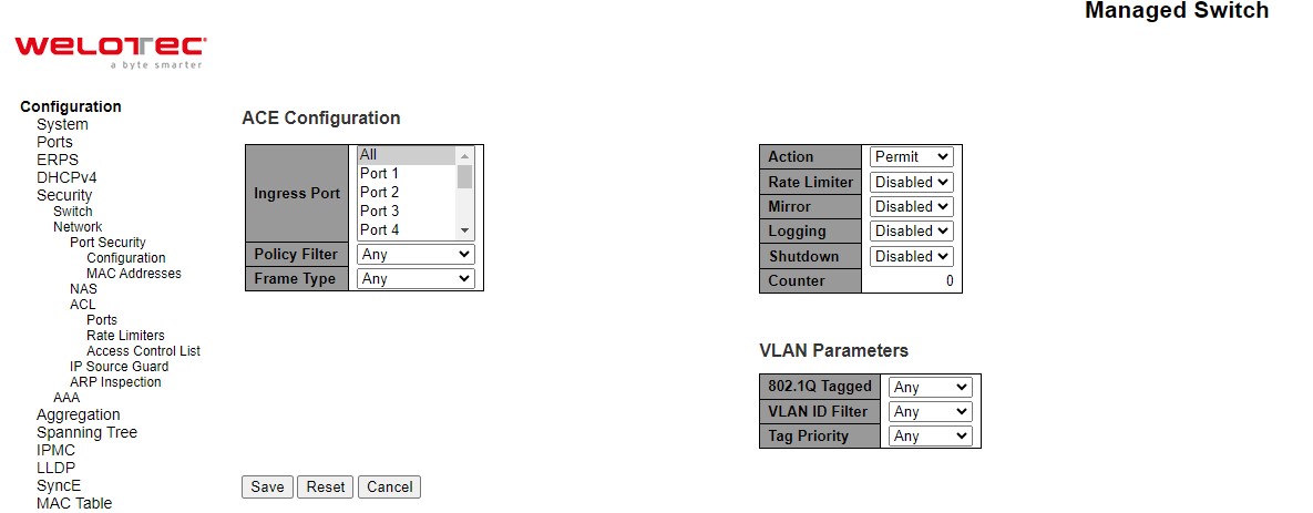
Table 2.39 Description of ACL Configuration:
Label |
Description |
|---|---|
Second Lookup |
Specify the second lookup operation of the ACE. |
Ingress Port |
Select the ingress port for which this ACE applies. All: The ACE applies to all port. Port n: The ACE applies to this port number, where n is the number of the switch port. |
Policy Filter |
Specify the policy number filter for this ACE. Any: No policy filter is specified. (policy filter status is “don’t-care”.) Specific: If you want to filter a specific policy with this ACE, choose this value. Two field for entering a policy value and bitmask appears. |
Policy Value |
When “Specific” is selected for the policy filter, you can enter a specific policy value. The allowed range is 0 to 63. |
Policy Bitmask |
When “Specific” is selected for the policy filter, you can enter a specific policy bitmask. The allowed range is 0x0 to 0x3f. Notice the usage of bitmask, if the binary bit value is “0”, it means this bit is “don’t-care”. The real matched pattern is [policy_value & policy_bitmask]. For example, if the policy value is 3 and the policy bitmask is 0x10(bit 0 is “don’t-care” bit), then policy 2 and 3 are applied to this rule. |
Frame Type |
Select the frame type for this ACE. These frame types are mutually exclusive. Any: Any frame can match this ACE. Ethernet Type: Only Ethernet Type frames can match this ACE. The IEEE 802.3 describes the value of Length/Type Field specifications to be greater than or equal to 1536 decimal (equal to 0600 hexadecimal) and the value should not be equal to 0x800(IPv4), 0x806(ARP) or 0x86DD(IPv6). ARP: Only ARP frames can match this ACE. Notice the ARP frames won’t match the ACE with ethernet type. IPv4: Only IPv4 frames can match this ACE. Notice the IPv4 frames won’t match the ACE with ethernet type. IPv6: Only IPv6 frames can match this ACE. Notice the IPv6 frames won’t match the ACE with Ethernet type. |
Action |
Specify the action to take with a frame that hits this ACE. Permit: The frame that hits this ACE is granted permission for the ACE operation. Deny: The frame that hits this ACE is dropped. Filter: Frames matching the ACE are filtered. |
Rate Limiter |
Specify the rate limiter in number of base units. The allowed range is 1 to 16. Disabled indicates that the rate limiter operation is disabled. |
Port Redirect |
Frames that hit the ACE are redirected to the port number specified here. The rate limiter will affect these ports. The allowed range is the same as the switch port number range. Disabled indicates that the port redirect operation is disabled and the specific port number of ‘Port Redirect’ can’t be setwhen action is permitted. |
Mirror |
Specify the mirror operation of this port. Frames matching the ACE are mirrored to the destination mirror port. The rate limiter will not affect frames on the mirror port. The allowed values are: Enabled: Frames received on the port are mirrored. Disabled: Frames received on the port are not mirrored. The default value is “Disabled”. |
Logging |
Specify the logging operation of the ACE. Notice that the logging message doesn’t include the 4 bytes CRC information. The allowed values are: Enabled: Frames matching the ACE are stored in the System Log. Disabled: Frames matching the ACE are not logged. Note: The logging feature only works when the packet length is less than 1518(without VLAN tags) and the System Log memory size and logging rate is limited. |
Shutdown |
Specify the port shut down operation of the ACE. The allowed values are:br>Enabled: If a frame matches the ACE, the ingress port will be disabled. Disabled: Port shut down is disabled for the ACE. Note: The shutdown feature only works when the packet length is less than 1518(without VLAN tags). |
Counter |
The counter indicates the number of times the ACE was hit by a frame. |
Table 2.40 Description of ACL Configuration with MAC Parameters:
Label |
Description |
|---|---|
SMAC Filter |
(Only displayed when the frame type is Ethernet Type or ARP.) Specify the source MAC filter for this ACE. Any: No SMAC filter is specified. (SMAC filter status is “don’t-care”.) Specific: If you want to filter a specific source MAC address with this ACE, choose this value. A field for entering a SMAC value appears. |
SMAC Value |
When “Specific” is selected for the SMAC filter, you can enter a specific source MAC address. The legal format is “xx-xx-xx-xx-xx-xx” or “xx.xx.xx.xx.xx.xx” or “xxxxxxxxxxxx” (x is a hexadecimal digit). A frame that hits this ACE matches this SMAC value. |
DMAC Filter |
Specify the destination MAC filter for this ACE. Any: No DMAC filter is specified. (DMAC filter status is “don’t-care”.) MC: Frame must be multicast. BC: Frame must be broadcast. UC: Frame must be unicast. Specific: If you want to filter a specific destination MAC address with this ACE, choose this value. A field for entering a DMAC value appears |
DMAC Value |
When “Specific” is selected for the DMAC filter, you can enter a specific destination MAC address. The legal format is “xx-xx-xx-xx-xx-xx” or “xx.xx.xx.xx.xx.xx” or “xxxxxxxxxxxx” (x is a hexadecimal digit). A frame that hits this ACE matches this DMAC value. |
Table 2.41 Description of ACL Configuration with VLAN Parameters
Label |
Description |
Factory Default |
|---|---|---|
802.1Q Tagged |
Specify whether frames can hit the action according to the 802.1Q tagged. The allowed values are: Any: Any value is allowed (“don’t-care”). Enabled: Tagged frame only. Disabled: Untagged frame only. The default value is “Any”. |
Any |
VLAN ID Filter |
Specify the VLAN ID filter for this ACE. Any: No VLAN ID filter is specified. (VLAN ID filter status is “don’t-care”.) Specific: If you want to filter a specific VLAN ID with this ACE, choose this value. A field for entering a VLAN ID number appears. |
Any |
VLAN ID |
When “Specific” is selected for the VLAN ID filter, you can enter a specific VLAN ID number. The allowed range is 1 to 4095. A frame that hits this ACE matches this VLAN ID value. |
1 |
Tag Priority |
Specify the tag priority for this ACE. A frame that hits this ACE matches this tag priority. The allowed number range is 0 to 7 or range 0-1, 2-3, 4-5, 6-7, 0-3 and 4-7. The value Any means that no tag priority is specified (tag priority is “don’t-care”.) |
Any |
Table 2.42 Description of ACL Configuration with ARP Parameters
Label |
Description |
Factory Default |
|---|---|---|
ARP/RARP |
Specify the available ARP/RARP opcode (OP) flag for this ACE. Any: No ARP/RARP OP flag is specified. (OP is “don’t-care”.) ARP: Frame must have ARP opcode set to ARP. RARP: Frame must have RARP opcode set to RARP. Other: Frame has unknown ARP/RARP Opcode flag. |
Any |
Request/Reply |
Specify the available Request/Reply opcode (OP) flag for this ACE. Any: No Request/Reply OP flag is specified. (OP is “don’t-care”.) Request: Frame must have ARP Request or RARP Request OP flag set. Reply: Frame must have ARP Reply or RARP Reply OP flag. |
Any |
Sender IP Filter |
Specify the sender IP filter for this ACE. Any: No sender IP filter is specified. (Sender IP filter is “don’t-care”.) Host: Sender IP filter is set to Host. Specify the sender IP address in the SIP Address field that appears. Network: Sender IP filter is set to Network. Specify the sender IP address and sender IP mask in the SIP Address and SIP Mask fields that appear. |
Any |
Sender IP Address |
When “Host” or “Network” is selected for the sender IP filter, you can enter a specific sender IP address in dotted decimal notation. Notice the invalid IP address configuration is acceptable too, for example, 0.0.0.0. Normally, an ACE with invalid IP address will explicitly adding deny action. |
- |
Sender IP Mask |
When “Network” is selected for the sender IP filter, you can enter a specific sender IP mask in dotted decimal notation. |
- |
Target IP Filter |
Specify the target IP filter for this ACE. Any: No target IP filter is specified. (Target IP filter is “don’t-care”.) Host: Target IP filter is set to Host. Specify the target IP address in the SIP Address field that appears. Network: Target IP filter is set to Network. Specify the target IP address and target IP mask in the SIP Address and SIP Mask fields that appear. |
Any |
Target IP Address |
When “Host” or “Network” is selected for the target IP filter, you can enter a specific target IP address in dotted decimal notation. Notice the invalid IP address configuration is acceptable too, for example, 0.0.0.0. Normally, an ACE with invalid IP address will explicitly adding deny action. |
- |
Target IP Mask |
When “Network” is selected for the target IP filter, you can enter a specific target IP mask in dotted decimal notation. |
- |
ARP Sender MAC Match |
Specify whether frames can hit the action according to their sender hardware address field (SHA) settings. 0: ARP frames where SHA is not equal to the SMAC address. 1: ARP frames where SHA is equal to the SMAC address. Any: Any value is allowed (“don’t-care”). |
Any |
RARP Target MAC Match |
Specify whether frames can hit the action according to their target hardware address field (THA) settings. 0: RARP frames where THA is not equal to the target MAC address. 1: RARP frames where THA is equal to the target MAC address. Any: Any value is allowed (“don’t-care”). |
Any |
IP/Ethernet Length |
Specify whether frames can hit the action according to their ARP/RARP hardware address length (HLN) and protocol address length (PLN) settings. 0: ARP/RARP frames where the HLN is not equal to Ethernet (0x06) or the (PLN) is not equal to IPv4 (0x04). 1: ARP/RARP frames where the HLN is equal to Ethernet (0x06) and the (PLN) is equal to IPv4 (0x04). Any: Any value is allowed (“don’t-care”). |
Any |
IP |
Specify whether frames can hit the action according to their ARP/RARP hardware address space (HRD) settings. 0: ARP/RARP frames where the HLD is not equal to Ethernet (1). 1: ARP/RARP frames where the HLD is equal to Ethernet (1). Any: Any value is allowed (“don’t-care”). |
Any |
Ethernet |
Specify whether frames can hit the action according to their ARP/RARP protocol address space (PRO) settings. 0: ARP/RARP frames where the PRO is not equal to IP (0x800). 1: ARP/RARP frames where the PRO is equal to IP (0x800). Any: Any value is allowed (“don’t-care”). |
Any |
Table 2.43 Description of ACL Configuration with IPv4 Parameters:
Label |
Description |
Factory Default |
|---|---|---|
IP Protocol Value |
When “Specific” is selected for the IP protocol value, you can enter a specific value. The allowed range is 0 to 255. A frame that hits this ACE matches this IP protocol value. |
- |
IP TTL |
Specify the Time-to-Live settings for this ACE. zero: IPv4 frames with a Time-to-Live field greater than zero must not be able to match this entry. non-zero: IPv4 frames with a Time-to-Live field greater than zero must be able to match this entry. Any Any value is allowed (“don’t-care”). |
Any |
IP Fragment |
Specify the fragment offset settings for this ACE. This involves the settings for the More Fragments (MF) bit and the Fragment Offset (FRAG OFFSET) field for an IPv4 frame. No: IPv4 frames where the MF bit is set or the FRAG OFFSET field is greater than zero must not be able to match this entry. Yes: IPv4 frames where the MF bit is set or the FRAG OFFSET field is greater than zero must be able to match this entry. Any: Any value is allowed (“don’t-care”). |
Any |
IP Option |
Specify the options flag setting for this ACE. No: IPv4 frames where the options flag is set must not be able to match this entry. Yes: IPv4 frames where the options flag is set must be able to match this entry. Any: Any value is allowed (“don’t-care”). |
Any |
SIP Filter |
Specify the source IP filter for this ACE. Any: No source IP filter is specified. (Source IP filter is “don’t-care”.) Host: Source IP filter is set to Host. Specify the source IP address in the SIP Address field that appears. Network:Source IP filter is set to Network. Specify the source IP address and source IP mask in the SIP Address and SIP Mask fields that appear. |
Any |
SIP Address |
When “Host” or “Network” is selected for the source IP filter, you can enter a specific SIP address in dotted decimal notation. Notice the invalid IP address configuration is acceptable too, for example, 0.0.0.0. Normally, an ACE with invalid IP address will explicitly adding deny action. |
- |
SIP Mask |
When “Network” is selected for the source IP filter, you can enter a specific SIP mask in dotted decimal notation. |
- |
DIP Filter |
Specify the destination IP filter for this ACE. Any: No destination IP filter is specified. (Destination IP filter is “don’t-care”.) Host: Destination IP filter is set to Host. Specify the destination IP address in the DIP Address field that appears. Network: Destination IP filter is set to Network. Specify the destination IP address and destination IP mask in the DIP Address and DIP Mask fields that appear. |
Any |
DIP Address |
When “Host” or “Network” is selected for the destination IP filter, you can enter a specific DIP address in dotted decimal notation. Notice the invalid IP address configuration is acceptable too, for example, 0.0.0.0. Normally, an ACE with invalid IP address will explicitly adding deny action. |
- |
DIP Mask |
When “Network” is selected for the destination IP filter, you can enter a specific DIP mask in dotted decimal notation. |
- |
Table 2.44 Description of ACL Configuration with IPv6 Parameters
Next Header Filter |
Specify the IPv6 next header filter for this ACE. Any: No IPv6 next header filter is specified (“don’t-care”). Specific: If you want to filter a specific IPv6 next header filter with this ACE, choose this value. A field for entering an IPv6 next header filter appears. ICMP: Select ICMP to filter IPv6 ICMP protocol frames. Extra fields for defining ICMP parameters will appear. These fields are explained later in this help file. UDP: Select UDP to filter IPv6 UDP protocol frames. Extra fields for defining UDP parameters will appear. These fields are explained later in this help file. TCP: Select TCP to filter IPv6 TCP protocol frames. Extra fields for defining TCP parameters will appear. These fields are explained later in this help file. |
Any |
|---|---|---|
Next Header Value |
When “Specific” is selected for the IPv6 next header value, you can enter a specific value. The allowed range is 0 to 255. A frame that hits this ACE matches this IPv6 protocol value. |
- |
SIP Filter |
Specify the source IPv6 filter for this ACE. Any: No source IPv6 filter is specified. (Source IPv6 filter is “don’t-care”.) Specific: Source IPv6 filter is set to Network. Specify the source IPv6 address and source IPv6 mask in the SIP Address fields that appear. |
Any |
SIP Address |
When “Specific” is selected for the source IPv6 filter, you can enter a specific SIPv6 address. The field only supported last 32 bits for IPv6 address. |
- |
SIP BitMask |
When “Specific” is selected for the source IPv6 filter, you can enter a specific SIPv6 mask. The field only supported last 32 bits for IPv6 address. Notice the usage of bitmask, if the binary bit value is “0”, it means this bit is “don’t-care”. The real matched pattern is [sipv6_address & sipv6_bitmask] (last 32 bits). For example, if the SIPv6 address is 2001::3 and the SIPv6 bitmask is 0xFFFFFFFE (bit 0 is “don’t-care” bit), then SIPv6 address 2001::2 and 2001::3 are applied to this rule |
- |
Hop Limit |
Specify the hop limit settings for this ACE. zero: IPv6 frames with a hop limit field greater than zero must not be able to match this entry. non-zero: IPv6 frames with a hop limit field greater than zero must be able to match this entry. Any: Any value is allowed (“don’t-care”). |
Any |
Table 2.45 Description of ACL Configuration with ICMP Parameters
Label |
Description |
Factory Default |
|---|---|---|
ICMP Type Filter |
Specify the ICMP filter for this ACE. Any: No ICMP filter is specified (ICMP filter status is “don’t-care”). Specific: If you want to filter a specific ICMP filter with this ACE, you can enter a specific ICMP value. A field for entering an ICMP value appears. |
Any |
ICMP Type Value |
When “Specific” is selected for the ICMP filter, you can enter a specific ICMP value. The allowed range is 0 to 255. A frame that hits this ACE matches this ICMP value. |
- |
ICMP Code Filer |
Specify the ICMP code filter for this ACE. Any: No ICMP code filter is specified (ICMP code filter status is “don’t-care”). Specific: If you want to filter a specific ICMP code filter with this ACE, you can enter a specific ICMP code value. A field for entering an ICMP code value appears. |
Any |
ICMP Code Value |
When “Specific” is selected for the ICMP code filter, you can enter a specific ICMP code value. The allowed range is 0 to 255. A frame that hits this ACE matches this ICMP code value. |
- |
Table 2.46 Description of ACL Configuration with TCP/UDP Parameters
Label |
Description |
Factory Default |
|---|---|---|
TCP/UDP Source Filter |
Specify the TCP/UDP source filter for this ACE. Any: No TCP/UDP source filter is specified (TCP/UDP source filter status is “don’t care”). Specific: If you want to filter a specific TCP/UDP source filter with this ACE, you can enter a specific TCP/UDP source value. A field for entering a TCP/UDP source value appears. Range: If you want to filter a specific TCP/UDP source range filter with this ACE, you can enter a specific TCP/UDP source range value. A field for entering a TCP/UDP source value appears. |
Any |
TCP/UDP Source No. |
When “Specific” is selected for the TCP/UDP source filter, you can enter a specific TCP/UDP source value. The allowed range is 0 to 65535. A frame that hits this ACE matches this TCP/UDP source value. |
- |
TCP/UDP Source Range |
When “Range” is selected for the TCP/UDP source filter, you can enter a specific TCP/UDP source range value. The allowed range is 0 to 65535. A frame that hits this ACE matches this TCP/UDP source value. |
- |
TCP/UDP Destination Filter |
Specify the TCP/UDP destination filter for this ACE. Any: No TCP/UDP destination filter is specified (TCP/UDP destination filter status is “don’t-care”). Specific: If you want to filter a specific TCP/UDP destination filter with this ACE, you can enter a specific TCP/UDP destination value. A field for entering a TCP/UDP destination value appears. Range: If you want to filter a specific range TCP/UDP destination filter with this ACE, you can enter a specific TCP/UDP destination range value. A field for entering a TCP/UDP destination value appears. |
Any |
TCP/UDP Destination Number |
When “Specific” is selected for the TCP/UDP destination filter, you can enter a specific TCP/UDP destination value. The allowed range is 0 to 65535. A frame that hits this ACE matches this TCP/UDP destination value. |
- |
TCP/UDP Destination Rang |
When “Range” is selected for the TCP/UDP destination filter, you can enter a specific TCP/UDP destination range value. The allowed range is 0 to 65535. A frame that hits this ACE matches this TCP/UDP destination value. |
- |
TCP FIN |
Specify the TCP “No more data from sender” (FIN) value for this ACE. 0: TCP frames where the FIN field is set must not be able to match this entry. 1: TCP frames where the FIN field is set must be able to match this entry. Any: Any value is allowed (“don’t-care”). |
Any |
TCP SYN |
Specify the TCP “”Synchronize sequence numbers” (SYN) value for this ACE. 0: TCP frames where the SYN field is set must not be able to match this entry. 1: TCP frames where the SYN field is set must be able to match this entry. Any: Any value is allowed (“don’t-care”). |
Any |
TCP RST |
Specify the TCP “Reset the connection” (RST) value for this ACE. 0: TCP frames where the RST field is set must not be able to match this entry. 1: TCP frames where the RST field is set must be able to match this entry. Any: Any value is allowed (“don’t-care”). |
Any |
TCP PSH |
Specify the TCP P “Push Function” (PSH) value for this ACE. 0: TCP frames where the PSH field is set must not be able to match this entry. 1: TCP frames where the PSH field is set must be able to match this entry. Any: Any value is allowed (“don’t-care”). |
Any |
TCP ACK |
Specify the TCP “Acknowledgment field significant” (ACK) value for this ACE. 0: TCP frames where the ACK field is set must not be able to match this entry. 1: TCP frames where the ACK field is set must be able to match this entry. Any: Any value is allowed (“don’t-care”). |
Any |
TCP URG |
Specify the TCP “Urgent Pointer field significant” (URG) value for this ACE. 0: URG frames where the FIN field is set must not be able to match this entry. 1: URG frames where the FIN field is set must be able to match this entry. Any: Any value is allowed (“don’t-care”). |
Any |
Table 2.47 Description of ACL Configuration with Ethernet Type Parameters:
Label |
Description |
Factory Default |
|---|---|---|
EtherType Filter |
Specify the Ethernet type filter for this ACE. Any: No EtherType filter is specified (EtherType filter status is “don’t-care”). Specific: If you want to filter a specific EtherType filter with this ACE, you can enter a specific EtherType value. A field for entering an EtherType value appears. |
- |
Ethernet Type Value |
When “Specific” is selected for the EtherType filter, you can enter a specific EtherType value. The allowed range is 0x600 to 0xFFFF but excluding 0x800(IPv4), 0x806(ARP) and 0x86DD(IPv6). A frame that hits this ACE matches this EtherType value. |
- |
IP Source Guard
IP Source Guard is a secure feature used to restrict IP traffic on DHCP snooping untrusted ports by filtering traffic based on the DHCP Snooping Table or manually configured IP Source Bindings. It helps prevent IP spoofing attacks when a host tries to spoof and use the IP address of another host. This is to prevent a malicious host from impersonating a legitimate host by assuming the legitimate host’s IP address.
IP Source Guard Configuration
IP Source Guard Configuration webpage is shown in Figure 2.60. For each port, select the option for Mode and Max Dynamic Clients under the Port Mode Configuration table. Table 2.48 describe the options under IP Source Guard Configuration.
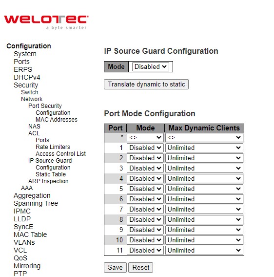
Table 2.48 Descriptions of Network IP Source Guard Configuration:
Label |
Description |
Factory Default |
|---|---|---|
IP Source Guard Configuration |
||
Mode |
Enable the Global IP Source Guard or disable the Global IP Source Guard. All configured ACEs will be lost when the mode is enabled. |
Disabled |
Port Mode Configuration |
||
Mode |
Specify IP Source Guard is enabled on which ports. Only when both Global Mode and Port Mode on a given port are enabled, IP Source Guard is enabled on this given port. |
Disabled |
Max Dynamic Clients |
Specify the maximum number of dynamic clients that can be learned on given port. This value can be 0, 1, 2 or unlimited. If the port mode is enabled and the value of max dynamic client is equal to 0, it means only allow the IP packets forwarding that are matched in static entries on the specific port. |
Unlimited |
Click the Save buttons to save changes. Click Reset buttons to undo any changes made locally and revert to previously saved values. Click Translate dynamic to static button to translate all dynamic entries to static entries.
IP Source Guard Static Table
The user can configure staic IP Source Guard Static rules in this webpage. The user can add a new entry to the IP Soruce Guard table as shown in Figure 2.61. The maximum number of rules is 112 on the switch. Table 2.49 summarizes the column labels for Static IP Source Guard Table.
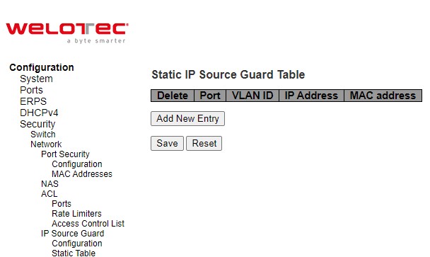
Table 2.49 Descriptions of Network IP Source Guard Static
Label |
Description |
Factory Default |
|---|---|---|
Delete |
Click entry Delete button to delete the entry. It will be deleted during the next save. |
|
Port |
The logical port for the settings. |
1 |
VLAN ID |
The VLAN Id for the entry. |
Null |
IP Address |
Allowed Source IP address. |
Null |
MAC Address |
Allowed Source MAC address. |
Null |
Click Add New Entry button to add a new entry to the Static IP Source Guard table. Click Save button to save changes. Click Reset button to undo any changes made locally and revert to previously saved values.
ARP Inspection
ARP Inspection is a secure feature. Several types of attacks can be launched against a host or devices connected to Layer 2 networks by “poisoning” the ARP caches. For example, man-in-the-middle attack occurs when a malicious node intercepts packets intended for other nodes by poisoning the ARP caches of its unsuspecting neighbours. To create the attack, the malicious node sends ARP requests or responses mapping another node’s IP address to its own MAC address. This feature is used to block such attacks. Only valid ARP requests and responses can go through the switch device. Figure 2.62 shows the list of submenus under the Security⭢Network⭢ARP Inspection. It contains Port Configuration, VLAN Configuration, Static Table and Dynamic Table.
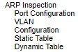
Port Configuration
To configure ARP Inspection for port(s) on the managed switch, the users can use the webpage shown in Figure 2.63. First, enable the ARP Inspection by selecting the Mode option. Then, configure the Mode, Check VLAN and Log Type for each port in the table below. Table 2.50 summarizes the descriptions of column labels of Port Mode Configuration.
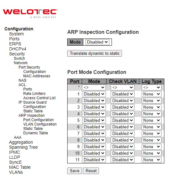
Table 2.50 Descriptions of ARP Inspection Port Configuration:
Label |
Description |
Factory Default |
|---|---|---|
ARP Inspection Configuration |
||
Mode |
Enable the Global ARP Inspection or disable the Global ARP Inspection. |
Disabled |
Port Mode Configuration |
||
Port |
Port Number |
- |
Mode |
Specify ARP Inspection is enabled on which ports. Only when both Global Mode and Port Mode on a given port are enabled, ARP Inspection is enabled on this given port. Possible modes are: Enabled: Enable ARP Inspection operation. Disabled: Disable ARP Inspection operation. |
Disabled |
Check VLAN |
If you want to inspect the VLAN configuration, you have to enable the setting of “Check VLAN”. The default setting of “Check VLAN” is disabled. When the setting of “Check VLAN” is disabled, the log type of ARP Inspection will refer to the port setting. And the setting of “Check VLAN” is enabled, the log type of ARP Inspection will refer to the VLAN setting. Possible setting of “Check VLAN” are: Enabled: Enable check VLAN operation. Disabled: Disable check VLAN operation. |
Disabled |
Log Type |
Only the Global Mode and Port Mode on a given port are enabled, and the setting of “Check VLAN” is disabled, the log type of ARP Inspection will refer to the port setting. There are four log types and possible types are: None: Log nothing. Deny: Log denied entries. Permit: Log permitted entries. ALL: Log all entries. |
None |
Click Save button to save changes. Click Reset button to undo any changes made locally and revert to previously saved values. Click Translate dynamic to static button to translate all dynamic entries to static entries.
VLAN Configuration
Figure 2.64 illustrates the ARP Inspection VLAN Configuration webpage. Each page can show up to 9999 entries from the VLAN table, default being 20. The user can change the number of visible entries through the “entries per page” input field. When first visited, the web page will show the first 20 entries from the beginning of the VLAN Table. The first displayed will be the one with the lowest VLAN ID found in the VLAN Table. The “VLAN” input fields allow the user to select the starting point in the VLAN Table.
Clicking the refresh button will update the displayed table starting from that or the closest next VLAN Table match. The right arrow button will use the next entry of the currently displayed VLAN entry as a basis for the next lookup. When the end is reached the warning, message is shown in the displayed table. Use the left arrow button to start over. Table 2.51 summarizes the column labels of the ARP Inspection VLAN table.
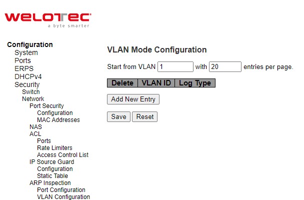
Table 2.51 Descriptions of ARP Inspection VLAN Table:
Label |
Description |
Factory Default |
|---|---|---|
Delete |
Click entry Delete button to delete the entry. |
- |
VLAN ID |
Specify ARP Inspection is enabled on which VLANs. First, you have to enable the port setting on Port mode configuration webpage (previous subsection). Only when both Global Mode and Port Mode on a given port are enabled, ARP Inspection is enabled on this given port. Second, you can specify which VLAN will be inspected on VLAN mode configuration web page. |
- |
Log Type |
The log type also can be configured on per VLAN setting. Possible types are: None: Log nothing. Deny: Log denied entries. Permit: Log permitted entries. ALL: Log all entries. |
None |
Click Add New Entry button to add a new entry to the ARP Inspection VLAN Table. Click Save button to save changes. Click Reset button to undo any changes made locally and revert to previously saved values.
Static Table
To configure Static ARP Inspection for port(s) on the managed switch, the users can use the webpage shown in Figure 2.65. After click the Add New Entry button, select the Port number from the drop down. Then, enter the VLAN ID, MAC Address and IP Address for each port to have static ARP Inspection. Table 2.52 summarizes the descriptions of column labels of Static ARP Inspection Table.
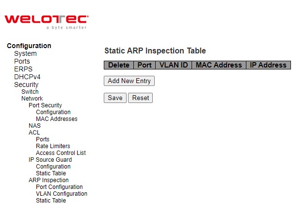
Table 2.52 Descriptions of Static ARP Inspection Table:
Label |
Description |
Factory Default |
|---|---|---|
Delete |
Check to delete the entry. It will be deleted during the next save. |
- |
Port |
The logical port for the settings. |
1 |
VLAN ID |
The VLAN ID for the settings. |
Null |
MAC Address |
Allowed Source MAC address in ARP request packets. |
Null |
IP Address |
Allowed Source IP address in ARP request packets. |
Null |
Click Save button to save changes. Click Reset button to undo any changes made locally and revert to previously saved values.
Dynamic Table
To configure Dynamic ARP Inspection for port(s) on the managed switch, the users can use the webpage shown in Figure 2.66. Entries in the Dynamic ARP Inspection Table are shown on this page. The Dynamic ARP Inspection Table contains up to 256 entries, and is sorted first by port, then by VLAN ID, then by MAC address, and then by IP address. All dynamic entries are learning from DHCP Snooping. Table 2.53 summarizes the descriptions of column labels of Dynamic ARP Inspection Table. Each webpage can show up to 99 entries from the Dynamic ARP Inspection table. The default maximum entries per page is 20. This can be selected through the “entries per page” input field. When first visited, the web page will show the first 20 entries from the beginning of the Dynamic ARP Inspection Table.
The “Start from port address”, “VLAN”, “MAC address” and “IP address” input fields allow the user to select the starting point in the Dynamic ARP Inspection Table. Clicking the Refresh button will update the displayed table starting from that or the closest next Dynamic ARP Inspection Table match. In addition, the two input fields will - upon a Refresh button click - assume the value of the first displayed entry, allowing for continuous refresh with the same start address. The >> button will use the last entry of the currently displayed table as a basis for the next lookup. When the end is reached the text “No more entries” is shown in the displayed table. Use the |<< button to start over.
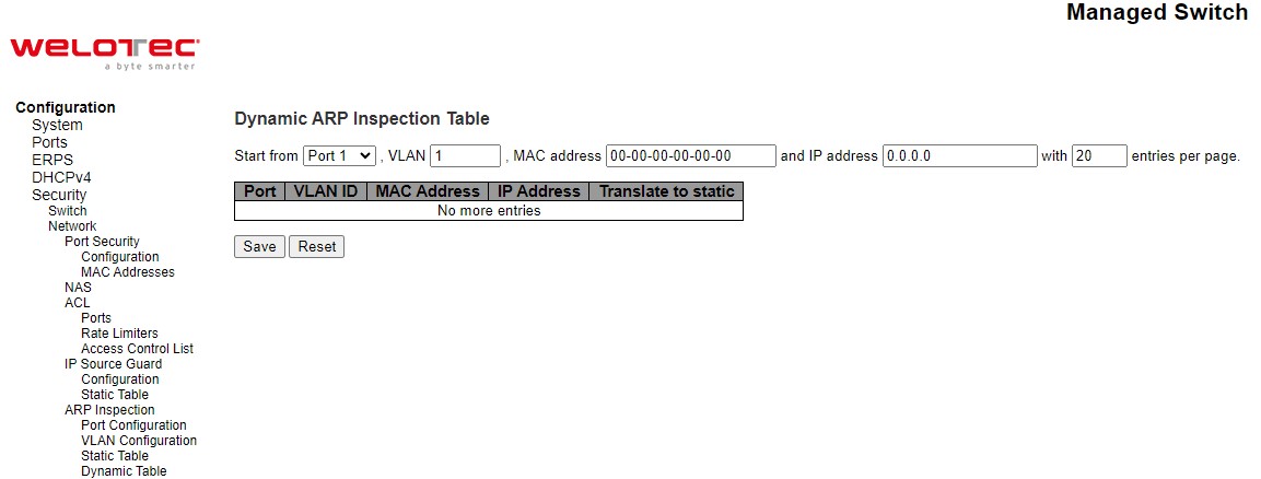
Table 2.53 Descriptions of ARP Inspection Dynamic Table:
Label |
Description |
Factory Default |
|---|---|---|
Port |
Switch Port Number for which the entries are displayed. |
Port1 |
VLAN ID |
VLAN-ID in which the ARP traffic is permitted. |
1 |
MAC Address |
User MAC address of the entry. |
00-00-00-00-00-00 |
IP Address |
User IP address of the entry. |
0.0.0.0 |
Translate to static |
Select the checkbox to translate the entry to static entry. |
- |
Click Save button to save changes. Click Reset button to undo any changes made locally and revert to previously saved values.
AAA
The authentication, authorization, and accounting (AAA) features allows you to verify the identity of, grant access to, and track the actions of users managing RSAES switches. The RSAES switches support Remote Access Dial-In User Service (RADIUS) or Terminal Access Controller Access Control System Plus (TACACS+) protocols. Based on the user ID and password combination that users provide, the RSAES switches perform local authentication or authorization using the local database or remote authentication or authorization using one or more AAA servers. A preshared secret key provides security for communication between the switch and AAA servers. You can configure a common secret key for all AAA servers or for only a specific AAA server.
AAA security provides the following services:
Authentication—Identifies users, including login and password dialog, challenge and response, messaging support, and encryption depending on the security protocol that you select. Authentication is the process of verifying the identity of the person or device accessing the RSAES switches. This process is based on the user ID and password combination provided by the entity trying to access the switch. The RSAES switches allow user to perform local authentication (using the local lookup database) or remote authentication (using one or more RADIUS or TACACS+ servers).
Authorization—Provides access control. AAA authorization is the process of assembling a set of attributes that describe what the user is authorized to perform. Authorization in RSAES switches is provided by attributes that are downloaded from AAA servers. Remote security servers, such as RADIUS and TACACS+, authorize users for specific rights by associating attribute-value (AV) pairs, which define those rights with the appropriate user.
Accounting—Provides the method for collecting information, logging the information locally, and sending the information to the AAA server for billing, auditing, and reporting. The accounting feature tracks and maintains a log of every management session used to access RSAES switches. You can use this information to generate reports for troubleshooting and auditing purposes. You can store accounting logs locally or send them to remote AAA servers.
AAA increases flexibility and control of access configuration, scalability, standardized authentication methods, such as RADIUS and TACACS+, and multiple backup devices.
RADIUS
RADIUS (Remote Authentication Dial in User Service) is an access server that uses authentication, authorization, and accounting (AAA) protocol for authentication and authorization. It is a distributed security system that secures remote access to networks and network services against unauthorized access. The RADIUS specification is described in [RFC 2865,] which obsoletes [RFC 2138.] Figure 2.67 shows the RADIUS Server Configuration webpage which allows the users to configure up to 5 RADIUS servers. It is divided into two parts: Global Configuration and Server Configuration. Table 2.54 summarizes the parameters for the RADIUS Server Configuration.
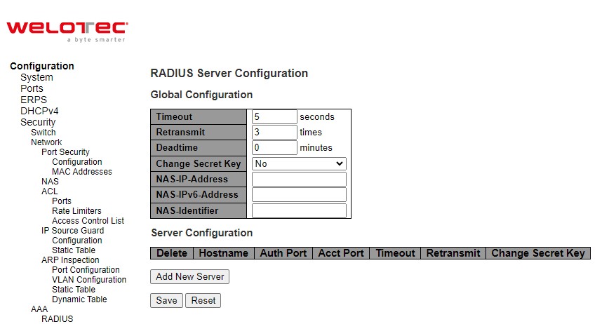
Table 2.54 Descriptions of AAA RADIUS:
Label |
Description |
Factory Default |
|---|---|---|
Global Configuration |
||
Timeout |
Timeout is the number of seconds, in the range 1 to 1000, to wait for a reply from a RADIUS server before retransmitting the request. |
5 |
Retransmit |
Retransmit is the number of times, in the range 1 to 1000, a RADIUS request is retransmitted to a server that is not responding. If the server has not responded after the last retransmit it is considered to be dead. |
3 |
Deadtime |
Deadtime, which can be set to a number between 0 to 1440 minutes, is the period during which the switch will not send new requests to a server that has failed to respond to a previous request. This will stop the switch from continually trying to contact a server that it has already determined as dead. Setting the Deadtime to a value greater than 0 (zero) will enable this feature, but only if more than one server has been configured. |
0 |
Change Secret Key |
Specify to change the secret key or not. When “Yes” is selected for the option, you can change the secret key - up to 63 characters long - shared between the RADIUS server and the switch. |
No |
NAS-IP-Address |
The IPv4 address to be used as attribute 4 in RADIUS Access-Request packets. If this field is left blank, the IP address of the outgoing interface is used. |
Null |
NAS-IPv6-Address |
The IPv6 address to be used as attribute 95 in RADIUS Access-Request packets. If this field is left blank, the IP address of the outgoing interface is used. |
Null |
NAS-Identifier |
The identifier - up to 253 characters long - to be used as attribute 32 in RADIUS Access-Request packets. If this field is left blank, the NAS-Identifier is not included in the packet. |
Null |
Server Configuration |
||
Delete |
To delete a RADIUS server entry, check this box. The entry will be deleted during the next Save. |
|
Hostname |
The IPv4/IPv6 address or hostname of the RADIUS server. |
Null |
Auth Port |
The UDP port to use on the RADIUS server for authentication. Set to 0 to disable authentication. |
1812 |
Acct Port |
The UDP port to use on the RADIUS server for accounting. Set to 0 to disable authentication. |
1813 |
Timeout |
This optional setting overrides the global timeout value. Leaving it blank will use the global timeout value. |
Null |
Retransmit |
This optional setting overrides the global retransmit value. Leaving it blank will use the global retransmit value. |
Null |
Change Secret Key |
Specify to change the secret key or not. When the checkbox is checked, you can change the setting overrides the global key. Leaving it blank will use the global key. |
Null |
After clicking on the Add New Server button to add a new RADIUS server, an empty row is added to the table, and the RADIUS server can be configured as needed. Up to 5 servers are supported. The Delete button can be used to undo the addition of the new server. Click Save button to save changes. Click Reset button to undo any changes made locally and revert to previously saved values.
TACACS+
TACACS+ is an acronym for Terminal Access Controller Access Control System Plus. It is a networking protocol which provides access control for routers, network access servers and other networked computing devices via one or more centralized servers. TACACS+ provides separate authentication, authorization and accounting services.
TACACS+ (Terminal Access Controller Access-Control System Plus) is a remote authentication protocol, which allows a remote access server to communicate with an authentication server to validate user access onto the network. TACACS+ allows a client to accept a username and password, and pass a query to a TACACS+ authentication server. Table 2.55 compares the differences between the RADIUS and TACACS+.
Table 2.55 Comparison of Authentication Server Settings between RADIUS and TACACS+:
RADIUS |
TACACS+ |
|
|---|---|---|
Transport Protocol |
UDP |
TCP |
Authentication and Authorization |
Separates AAA |
Combines authentication and authorization |
Multiprotocol Support |
No |
Yes, support AppleTalk Remote Access (ARA) and NetBIOS protocol |
Confidentiality |
Only password is encrypted |
Entire packet is encrypted |
Figure 2.68 shows the TACACS+ Server Configuration webpage. It consists of Global Configuration and Server Configuration parts. Table 2.56 summarizes descriptions of parameters for setting up the TACACS+ Server.
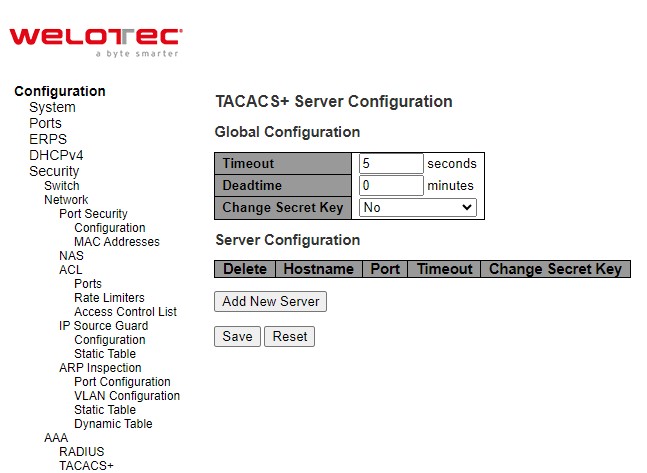
Table 2.56 Descriptions of AAA RADIUS:
Label |
Description |
Factory Default |
|---|---|---|
Global Configuration |
||
Timeout |
Timeout is the number of seconds, in the range 1 to 1000, to wait for a reply from a TACACS+ server before it is considered to be dead. |
5 |
Deadtime |
Deadtime, which can be set to a number between 0 to 1440 minutes, is the period during which the switch will not send new requests to a server that has failed to respond to a previous request. This will stop the switch from continually trying to contact a server that it has already determined as dead. Setting the Deadtime to a value greater than 0 (zero) will enable this feature, but only if more than one server has been configured. |
0 |
Change Secret Key |
Specify to change the secret key or not. When “Yes” is selected for the option, you can change the secret key - up to 63 characters long - shared between the TACACS+ server and the switch. |
No |
Server Configuration |
||
Delete |
To delete a TACACS+ server entry, check this box. The entry will be deleted during the next Save. |
|
Hostname |
The IPv4/IPv6 address or hostname of the TACACS+ server. |
Null |
Port |
The TCP port to use on the TACACS+ server for authentication. |
49 |
Timeout |
This optional setting overrides the global timeout value. Leaving it blank will use the global timeout value. |
Null |
Change Secret Key |
Specify to change the secret key or not. When the checkbox is checked, you can change the setting overrides the global key. Leaving it blank will use the global key. |
Null |
After clicking on the Add New Server button to add a new TACACS+ server, an empty row is added to the table, and the TACACS+ server can be configured as needed. Up to 5 servers are supported. The Delete button can be used to undo the addition of the new server. Click Save button to save changes. Click Reset button to undo any changes made locally and revert to previously saved values.
Aggregation
Aggregation is a technique to use multiple ports in parallel to increase the link speed beyond the limits of a port and to increase the redundancy for higher availability. Welotec’s RSAES allows the aggregation on its ports. Figure 2.69 lists the submenus under the Configuration⭢Aggregation.

Common
The webpage in Figure 2.70 is used to configure the Aggregation hash mode. The configured mode is applied to the whole network elements. Four contributors can be selected and used to create the hash code which are Source MAC Address, Destination MAC Address, IP Address, and TCP/UDP Port Number. Table 2.57 summarizes the descriptions of hash code contributors under the Common Aggregation Configuration.
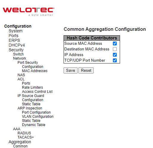
Table 2.57 Descriptions of Common Aggregation Configuration:
Label |
Description |
Factory Default |
|---|---|---|
Hash Code Contributors |
||
Source MAC Address |
The Source MAC address can be used to calculate the destination port for the frame. Check to enable the use of the Source MAC address, or uncheck to disable. By default, Source MAC Address is enabled. |
Checked |
Destination MAC Address |
The Destination MAC Address can be used to calculate the destination port for the frame. Check to enable the use of the Destination MAC Address, or uncheck to disable. By default, Destination MAC Address is disabled. |
Unchecked |
IP Address |
The IP address can be used to calculate the destination port for the frame. Check to enable the use of the IP Address, or uncheck to disable. By default, IP Address is enabled. |
Checked |
TCP/UDP Port Number |
The TCP/UDP port number can be used to calculate the destination port for the frame. Check to enable the use of the TCP/UDP Port Number, or uncheck to disable. By default, TCP/UDP Port Number is enabled. |
Checked |
Click Save button to save changes. Click Reset button to undo any changes made locally and revert to previously saved values.
Groups
This webpage allows the user to aggregate different port(s) to an aggregation group. The Aggregation Group Configuration is shown in Figure 2.71. After selecting which port number(s) belong to which aggregation group ID, the user can choose the mode of aggregation group from Disabled, Static, LACP (Active), LACP (Passive). Table 2.58 summarizes the descriptions of Aggregation Group Configuration.
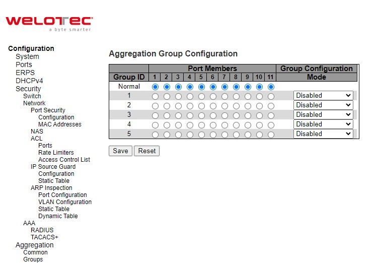
Table 2.58 Descriptions of Aggregation Group Configuration:
Label |
Description |
Factory Default |
|---|---|---|
Group ID |
Indicates the aggregation group ID for the settings contained in the same row. Group ID “Normal” indicates there is no aggregation. Only one group ID is valid per port. |
- |
Port Members |
Each switch port is listed for each group ID. Select a radio button to include a port in an aggregation, or clear the radio button to remove the port from the aggregation. By default, no ports belong to any aggregation group. Only full duplex ports can join an aggregation and ports must be in the same speed in each group. |
Unclicked |
Mode |
This parameter determines the mode for the aggregation group. Disabled: The group is disabled. Static: The group operates in static aggregation mode. LACP (Active): The group operates in LACP active aggregation mode. See IEEE 801.AX-2014, Section 6.4.1 for details. LACP (Passive): The group operates in LACP passive aggregation mode. See IEEE 801.AX-2014, Section 6.4.1 for details. |
Disabled |
Click Save button to save changes. Click Reset button to undo any changes made locally and revert to previously saved values.
LACP
The users have an option to enable Link Aggregation Control Protocol (LACP) which is an IEEE standard (IEEE 802.3ad, IEEE 802.1AX-2008) by selecting on LACP aggregation mode in previous subsection. LACP allows the managed switch to negotiate an automatic bundling of links by sending LACP packets to the LACP partner or another device that is directly connected to the managed switch and also implements LACP. The LACP packets will be sent within a multicast group MAC address. If LACP finds a device on the other end of the link that also has LACP enabled, it will also independently send packets along the same links enabling the two units to detect multiple links between themselves and then combine them into a single logical link. During the detection period LACP packets are transmitted every second. Subsequently, keep alive mechanism for link membership will be sent periodically. Each port in the group can also operate in either LACP active or LACP passive modes. The LACP active mode means that the port will enable LACP unconditionally, while LACP passive mode means that the port will enable LACP only when an LACP partner is detected. Note that in active mode LACP port will always send LACP packets along the configured links. In passive mode however, LACP port acts as “speak when spoken to”, and therefore can be used as a way of controlling accidental loops (as long as the other device is in active mode).
Figure 2.72 shows the LACP System Configuration webpage. It allows the user to configure the System Priority and LACP System Configuration. Table 2.59 summarizes the descriptions of LACP Aggregation Configuration.
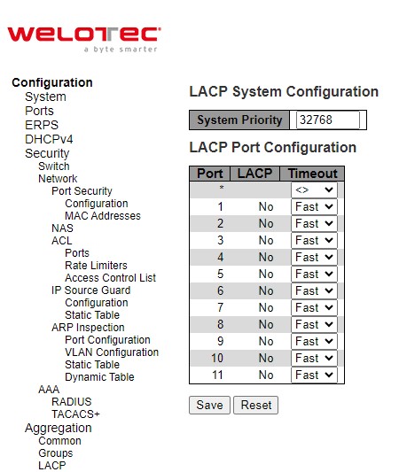
Table 2.59 Descriptions of LACP Aggregation Configuration:
Label |
Description |
Factory Default |
|---|---|---|
Port |
The switch port number. |
- |
LACP |
Show whether LACP is currently enabled on this switch port. |
No |
Timeout |
The Timeout controls the period between BPDU transmissions. Fast will transmit LACP packets each second, while Slow will wait for 30 seconds before sending a LACP packet. |
Fast |
Click Save button to save changes. Click Reset button to undo any changes made locally and revert to previously saved values.
Spanning Tree
IEEE 802.1D Standard spanning tree functionality is supported by Welotec’s RSAES managed switches.
Spanning Tree Protocol (STP) provides a function to prevent switching loops and broadcast radiation at the OSI layer 2. A switching loop occurs in a network when there are multiple connections or redundant paths between two network switches or at least two ports are connected on both sides of the two network switches. The switching loop can create a broadcast radiation, which is the accumulation of broadcast and multicast traffics in a computer network. As broadcast and multicast messages are forwarded by bridges/switches to every port, the bridges/switches will repeatedly rebroadcast the broadcast messages, and this accumulation of traffic can flood the network. STP creates a spanning tree topology and disables those links of the network that are not part of the spanning tree, which leaves only a single active path between two nodes. This function can avoid flooding and increase network efficiency. Therefore, Welotec’s managed switches deploy spanning tree as a tool when the users set up connection or port redundancy or fault-tolerance in their network.
RSTP (Rapid Spanning Tree Protocol), IEEE 802.1W, is also supported in Welotec’s managed switches. It is an evolution of the STP, but it is still backwards compatible with standard STP. RSTP has the advantage over the STP. When there is a topology change such as link failure in the network, the RSTP will converge significantly faster to a new spanning tree topology. RSTP improves convergence on point-to-point links by reducing the Max-Age time to 3 times Hello interval, removing the STP listening state, and exchanging a handshake between two switches to quickly transition the port to forwarding state.
MSTP (Multiple Spanning Tree Protocol) is also a standard defined by the IEEE 802.1s that allows multiple VLANs to be mapped to a single spanning tree instance called MST Instance, which will provide multiple pathways across the network. It is compatible with STP and RSTP. To support lager network, MSTP groups bridges/switches into regions that appear as a single bridge to other devices. Within each region, there can be multiple MST instances. MSTP shares common parameters as RSTP such as port path costs. MSTP also help prevent switching loop and has rapid convergence when there is a topology change. It is possible to have different forwarding paths for different MST instances. This enables load balancing of network traffic across redundant links.
The following subsections describe how to setup the spanning tree protocol (STP), rapid spanning tree protocol (RSTP), and Multiple Spanning Tree Protocol (MSTP). The Spanning Tree menu consists of Bridge Settings, MSTI Mapping, MSTI Priorities, CIST Ports, and MSTI Ports.
Bridge Settings
To select a variant of Spanning Tree Protocol, the user can select the Protocol Version and set related parameters for that particular protocol version in this STP Bridge Configuration webpage as shown in Figure 2.73. The settings are grouped into Basic Settings and Advanced Settings. These settings are used by all STP Bridge instances in the managed switch. Table 2.60 summarizes the description of each parameter under the STP Bridge Configuration webpage.
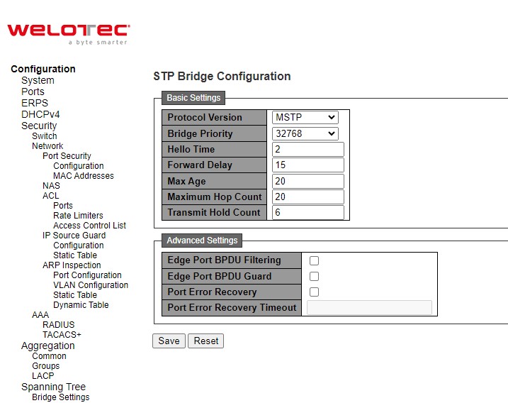
Table 2.60 Descriptions of Bridge Settings Configuration of Spanning Tree:
Label |
Description |
Factory Default |
|---|---|---|
Basic Settings |
||
Protocol Version |
The MSTP / RSTP / STP protocol version setting. |
MSTP |
Bridge Priority |
Controls the bridge priority. Lower numeric values have better priority. The bridge priority plus the MSTI instance number, concatenated with the 6-byte MAC address of the switch forms a Bridge Identifier. For MSTP operation, this is the priority of the CIST. Otherwise, this is the priority of the STP/RSTP bridge. |
32768 |
Hello Time |
The interval between sending STP BPDU’s. Valid values are in the range 1 to 10 seconds, default is 2 seconds. Note: Changing this parameter from the default value is not recommended, and may have adverse effects on your network. |
2 |
Forward Delay |
The delay used by STP Bridges to transit Root and Designated Ports to Forwarding (used in STP compatible mode). Valid values are in the range 4 to 30 seconds. |
15 |
Max Age |
The maximum age of the information transmitted by the Bridge when it is the Root Bridge. Valid values are in the range 6 to 40 seconds, and MaxAge must be <= (FwdDelay-1)*2. |
20 |
Maximum Hop Count |
This defines the initial value of remaining Hops for MSTI information generated at the boundary of an MSTI region. It defines how many bridges a root bridge can distribute its BPDU information to. Valid values are in the range 6 to 40 hops. |
20 |
Transmit Hold Count |
The number of BPDU’s a bridge port can send per second. When exceeded, transmission of the next BPDU will be delayed. Valid values are in the range 1 to 10 BPDU’s per second. |
6 |
Advanced Settings |
||
Edge Port BPDU Filtering |
Control whether a port explicitly configured as Edge will transmit and receive BPDUs. |
Unclicked |
Edge Port BPDU Guard |
Control whether a port explicitly configured as Edge will disable itself upon reception of a BPDU. The port will enter the error-disabled state, and will be removed from the active topology. |
Unclicked |
Port Error Recovery |
Control whether a port in the error-disabled state automatically will be enabled after a certain time. If recovery is not enabled, ports have to be disabled and re-enabled for normal STP operation. The condition is also cleared by a system reboot. |
Unclicked |
Port Error Recovery Timeout |
The time to pass before a port in the error-disabled state can be enabled. Valid values are between 30 and 86400 seconds (24 hours). |
Null |
Click Save button to save changes. Click Reset button to undo any changes made locally and revert to previously saved values.
MSTI Mapping
MSTI Mapping webpage is shown in Figure 2.74. This page allows the user to inspect and/or change the current STP MSTI bridge VLAN Mapping configurations. The MSTI Configuration consists of Configuration Identification part and MSTI Mapping part. Table 2.61 summarizes the description of parameters under MSTI Configuration.
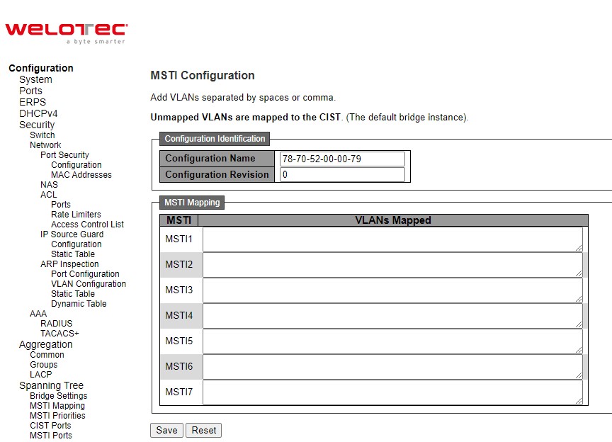
Table 2.61 Descriptions of Bridge Priorities Configuration of Spanning Tree:
Label |
Description |
Factory Default |
|---|---|---|
Configuration Identification |
||
Configuration Name |
The MSTP / RSTP / STP protocol version setting. |
MSTP |
Bridge Priority |
The name identifying the VLAN to MSTI mapping. Bridges must share the name and revision (see below), as well as the VLAN-to MSTI mapping configuration in order to share spanning trees for MSTI’s (Intra-region). The name is at most 32 characters. |
DUT’s MAC address |
Configuration Revision |
The revision of the MSTI configuration named above. This must be an integer between 0 and 65535. |
0 |
MSTI Mapping |
||
MSTI |
The bridge instances. The CIST is not available for explicit mapping, as it will receive the VLANs not explicitly mapped. |
|
VLANs Mapped |
The list of VLANs mapped to the MSTI. The VLANs can be given as a single (xx, xx being between 1 and 4094) VLAN, or a range (xx-yy), each of which must be separated with comma and/or space. A VLAN can only be mapped to one MSTI. An unused MSTI should just be left empty. (I.e., not having any VLANs mapped to it.) Example: 2, 5, 20-40. |
Null |
Click Save button to save changes. Click Reset button to undo any changes made locally and revert to previously saved values.
MSTI Priorities
MSTI Priorities webpage is shown in Figure 2.75. This page allows the user to inspect and/or change the current STP MSTI bridge instance priority configurations. Table 2.62 summarizes the description of parameters under MSTI Configuration.
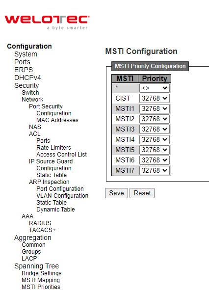
Table 2.62 Descriptions of Bridge MSTI Priorities Configuration of Spanning Tree:
Label |
Description |
Factory Default |
|---|---|---|
MSTI |
The bridge instances. The CIST is the default instance, which is always active. |
- |
Priority |
Controls the bridge priority. Lower numeric values have better priority. The bridge priority plus the MSTI instance number, concatenated with the 6-byte MAC address of the switch forms a Bridge Identifier |
32768 |
Click Save button to save changes. Click Reset button to undo any changes made locally and revert to previously saved values.
CIST Ports
The CIST Ports webpage in Figure 2.76 allows the user to inspect and change the current STP CIST port configurations. This page contains settings for physical and aggregated ports. There are two tables: CIST Aggregated Port Configuration and CIST Normal Port Configuration. Table 2.63 provides the descriptions of all column labels of the two tables under the STP CIST Port Configuration.
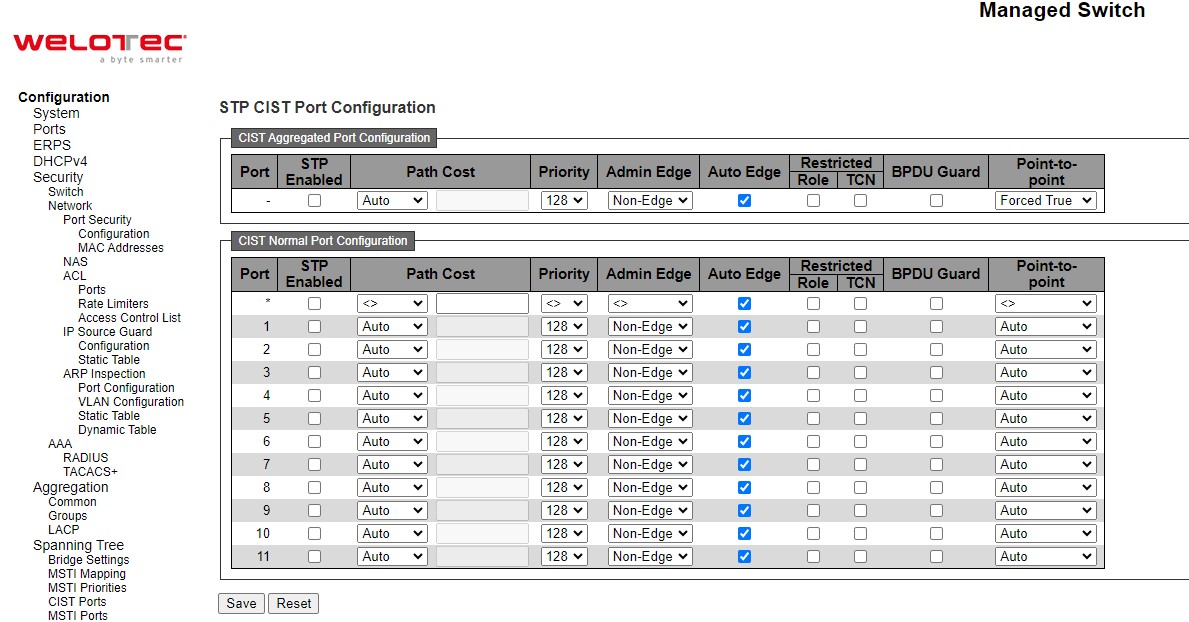
Table 2.63 Descriptions of CIST Ports Configuration of Spanning Tree:
Label |
Description |
Factory Default |
|
|---|---|---|---|
CIST Aggregated Port Configuration |
|||
Port |
The switch port number of the logical STP port. |
- |
|
STP Enabled |
Controls whether STP is enabled on this switch port. |
Checked |
|
Path Cost |
Controls the path cost incurred by the port. The Auto setting will set the path cost as appropriate by the physical link speed, using the 802.1D recommended values. Using the Specific setting, a user-defined value can be entered. The path cost is used when establishing the active topology of the network. Lower path cost ports are chosen as forwarding ports in favour of higher path cost ports. Valid values are in the range 1 to 200000000. |
Auto |
|
Priority |
Controls the port priority. This can be used to control priority of ports having identical port cost. (See above). Lower priority is better. |
128 |
|
Admin Edge |
Admin Edge or State Flag. Operational flag describing whether the port is connecting directly to edge devices. (No Bridges attached). Transition to the forwarding state is faster for edge ports (having operEdge true) than for other ports. The value of this flag is based on AdminEdge and AutoEdge fields. This flag is displayed as Edge in Monitor⭢Spanning Tree ⭢ STP Detailed Bridge Status. |
Non-Edge |
|
Auto Edge |
Controls whether the bridge should enable automatic edge detection on the bridge port. This allows operEdge to be derived from whether BPDU’s are received on the port or not. |
Checked |
|
Restricted |
Role |
If enabled, causes the port not to be selected as Root Port for the CIST or any MSTI, even if it has the best spanning tree priority vector. Such a port will be selected as an Alternate Port after the Root Port has been selected. If set, it can cause lack of spanning tree connectivity. It can be set by a network administrator to prevent bridges external to a core region of the network influence the spanning tree active topology, possibly because those bridges are not under the full control of the administrator. This feature is also known as Root Guard. |
Unchecked |
TCN |
If enabled, causes the port not to propagate received topology change notifications and topology changes to other ports. If set it can cause temporary loss of connectivity after changes in a spanning tree’s active topology as a result of persistently incorrect learned station location information. It is set by a network administrator to prevent bridges external to a core region of the network, causing address flushing in that region, possibly because those bridges are not under the full control of the administrator or the physical link state of the attached LANs transits frequently. |
Unchecked |
|
BPDU Guard |
If enabled, causes the port to disable itself upon receiving valid BPDU’s. Contrary to the similar bridge setting, the port Edge status does not affect this setting. A port entering error-disabled state due to this setting is subject to the bridge Port Error Recovery setting as well. |
Unchecked |
|
Point-to-point |
Controls whether the port connects to a point-to-point LAN rather than to a shared medium. This can be automatically determined, or forced either true or false. Transition to the forwarding state is faster for point-to-point LANs than for shared media. |
Force True |
|
CIST Normal Port Configuration |
|||
Port |
The switch port number of the logical STP port. |
- |
|
STP Enabled |
Controls whether STP is enabled on this switch port. |
Checked |
|
Path Cost |
Controls the path cost incurred by the port. The Auto setting will set the path cost as appropriate by the physical link speed, using the 802.1D recommended values. Using the Specific setting, a user-defined value can be entered. The path cost is used when establishing the active topology of the network. Lower path cost ports are chosen as forwarding ports in favour of higher path cost ports. Valid values are in the range 1 to 200000000. |
Auto |
|
Priority |
Controls the port priority. This can be used to control priority of ports having identical port cost. (See above). |
128 |
|
Admin Edge |
Admin Edge or State Flag. Operational flag describing whether the port is connecting directly to edge devices. (No Bridges attached). Transition to the forwarding state is faster for edge ports (having operEdge true) than for other ports. The value of this flag is based on AdminEdge and AutoEdge fields. This flag is displayed as Edge in Monitor⭢Spanning Tree ⭢ STP Detailed Bridge Status. |
Non-Edge |
|
Auto Edge |
Controls whether the bridge should enable automatic edge detection on the bridge port. This allows operEdge to be derived from whether BPDU’s are received on the port or not. |
Checked |
|
Restricted |
Role |
If enabled, causes the port not to be selected as Root Port for the CIST or any MSTI, even if it has the best spanning tree priority vector. Such a port will be selected as an Alternate Port after the Root Port has been selected. If set, it can cause lack of spanning tree connectivity. It can be set by a network administrator to prevent bridges external to a core region of the network influence the spanning tree active topology, possibly because those bridges are not under the full control of the administrator. This feature is also known as Root Guard. |
Unchecked |
TCN |
If enabled, causes the port not to propagate received topology change notifications and topology changes to other ports. If set it can cause temporary loss of connectivity after changes in a spanning tree’s active topology as a result of persistently incorrect learned station location information. It is set by a network administrator to prevent bridges external to a core region of the network, causing address flushing in that region, possibly because those bridges are not under the full control of the administrator or the physical link state of the attached LANs transits frequently. |
Unchecked |
|
BPDU Guard |
If enabled, causes the port to disable itself upon receiving valid BPDU’s. Contrary to the similar bridge setting, the port Edge status does not affect this setting. A port entering error-disabled state due to this setting is subject to the bridge Port Error Recovery setting as well. |
Unchecked |
|
Point-to-point |
Controls whether the port connects to a point-to-point LAN rather than to a shared medium. This can be automatically determined, or forced either true or false. Transition to the forwarding state is faster for point-to-point LANs than for shared media. |
Auto |
Click Save button to save changes. Click Reset button to undo any changes made locally and revert to previously saved values.
MSTI Ports
The MSTI Ports webpage as shown in Figure 2.77 allows the user to inspect and/or change the current STP MSTI port configurations. An MSTI port is a virtual port, which is instantiated separately for each active CIST (physical) port for each MSTI instance configured on and applicable to the port. The MSTI instance must be selected before displaying actual MSTI port configuration options. After selecting a desired MSTI and clicking on the Get button, the webpage is updated as shown in Figure 2.78. The updated page contains MSTI port settings for physical and aggregated ports. Table 2.64 summarizes the descriptions of MSTI Port Configuration.
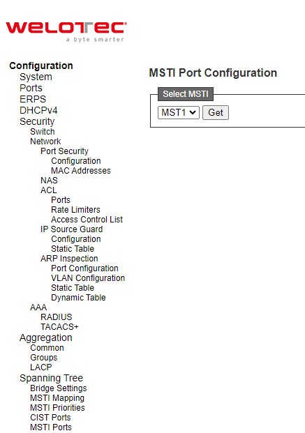
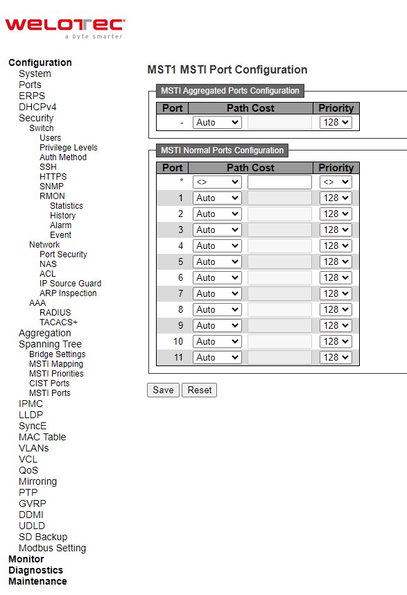
Table 2.64 Descriptions of MSTI Configuration of Spanning Tree:
Label |
Description |
Factory Default |
|---|---|---|
Port |
The switch port number of the corresponding STP CIST (and MSTI) port. |
MSTI |
Path Cost |
Controls the path cost incurred by the port. The Auto setting will set the path cost as appropriate by the physical link speed, using the 802.1D recommended values. Using the Specific setting, a user defined value can be entered. The path cost is used when establishing the active topology of the network. Lower path cost ports are chosen as forwarding ports in favour of higher path cost ports. Valid values are in the range 1 to 200000000. |
Auto |
Priority |
Controls the port priority. This can be used to control priority of ports having identical port cost. Lower priority is better. |
128 |
Click Save button to save changes. Click Reset button to undo any changes made locally and revert to previously saved values.
IPMC
IP MultiCast (IPMC) menu can be configured using the submenus as shown in Figure 2.79. The IGMP Snooping is used for IPv4, while the MLD Snooping is used for IPv6.
IGMP Snooping
IGMP is an acronym for Internet Group Management Protocol. It is a communications protocol used to manage the membership of Internet Protocol multicast groups. IGMP is used by IP hosts and adjacent multicast routers to establish multicast group memberships. It is an integral part of the IP multicast specification, like ICMP for unicast connections. IGMP can be used for online video and gaming, and allows more efficient use of resources when supporting these uses.
Basic Configuration
IGMP Snooping⭢Basic Configuration webpage provides IGMP Snooping related configuration as shown in Figure 2.80. The page consists of Global Configuration and Port Related Configuration. Table 2.65 summarizes the descriptions of IGMP Snooping Configuration.
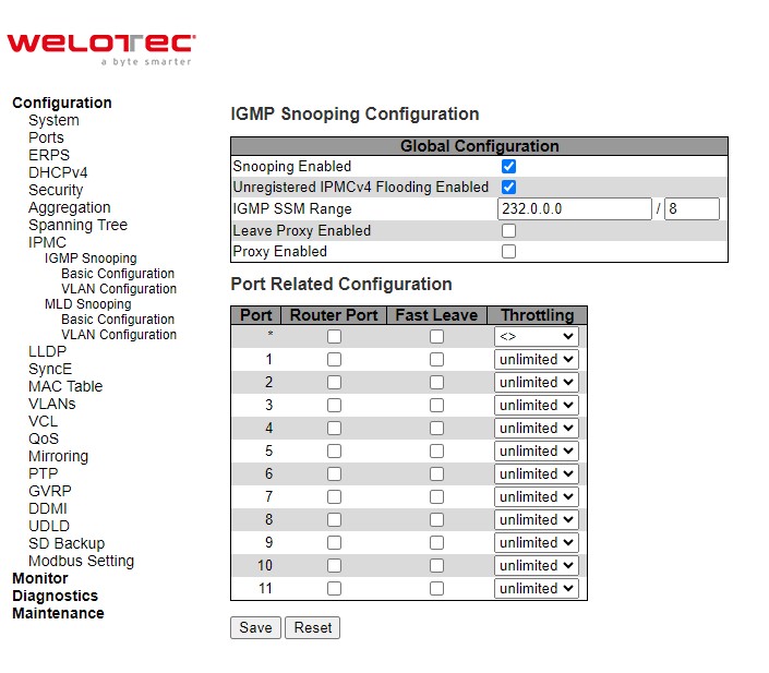
Table 2.65 Descriptions of IGMP Snooping of an IPMC Profile:
Label |
Description |
Factory Default |
|---|---|---|
IGMP Snooping Configuration |
||
Snooping Enabled |
Enable the Global IGMP Snooping. |
Clicked |
Unregistered IPMCv4 Flooding Enabled |
Enable unregistered IPMCv4 traffic flooding. The flooding control takes effect only when IGMP Snooping is enabled. When IGMP Snooping is disabled, unregistered IPMCv4 traffic flooding is always active in spite of this setting. |
Clicked |
IGMP SSM Range |
SSM (Source-Specific Multicast) Range allows the SSM-aware hosts and routers run the SSM service model for the groups in the address range. Assign valid IPv4 multicast address as prefix with a prefix length (from 4 to 32) for the range. |
232.0.0.0 / 8 |
Leave Proxy Enabled |
Enable IGMP Leave Proxy. This feature can be used to avoid forwarding unnecessary leave messages to the router side. |
Unclicked |
Proxy Enabled |
Enable IGMP Proxy. This feature can be used to avoid forwarding unnecessary join and leave messages to the router side. |
Unclicked |
Port Related Configuration |
||
Router Port |
Specify which ports act as router ports. A router port is a port on the Ethernet switch that leads towards the Layer 3 multicast device or IGMP querier. If an aggregation member port is selected as a router port, the whole aggregation will act as a router port. |
Unclicked |
Fast Leave |
Enable the fast leave on the port. System will remove group record and stop forwarding data upon receiving the IGMPv2 leave message without sending last member query messages. It is recommended to enable this feature only when a single IGMPv2 host is connected to the specific port. |
Unclicked |
Throttling |
Enable to limit the number of multicast groups to which a switch port can belong. |
unlimited |
Click Save button to save changes. Click Reset button to undo any changes made locally and revert to previously saved values.
VLAN Configuration
IGMP Snooping VLAN Configuration is shown in Figure 2.81. Note that the user needs to enter IP configuration page (System⭢IP⭢Add IP interface) to setup IP interface first before the creation of IGMP VLAN interface. The IGMP Snooping VLAN table is also displayed on this webpage. Each page can show up to 99 entries from the VLAN table, default being 20, selected through the “entries per page” input field. When first visited, the web page will show the first 20 entries from the beginning of the VLAN Table. The first displayed will be the one with the lowest VLAN ID found in the VLAN Table. The “VLAN” input fields allow the user to select the starting point in the VLAN Table. Clicking the Refresh button will update the displayed table starting from that or the next closest VLAN Table match. The >> button will use the last entry of the currently displayed entry as a basis for the next lookup. When the end is reached the text “No more entries” is shown in the displayed table. Use the << button to start over. Table 2.66 summarizes the descriptions of the IGMP Snooping VLAN Configuration.
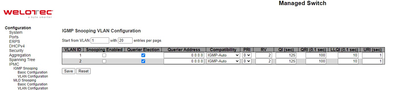
Table 2.66 Descriptions of IGMP Snooping’s VLAN Configuration for an IPMC Profile:
Label |
Description |
Factory Default |
|---|---|---|
VLAN ID |
The VLAN ID of the entry. |
1 |
Snooping Enabled |
Enable the per-VLAN IGMP Snooping. Up to 8 VLANs can be selected for IGMP Snooping. |
Unchecked |
Querier Election |
Enable to join IGMP Querier election in the VLAN. Disable to act as an IGMP Non-Querier. |
Checked |
Querier Address |
Define the IPv4 address as source address used in IP header for IGMP Querier election. When the Querier address is not set, system uses IPv4 management address of the IP interface associated with this VLAN. When the IPv4 management address is not set, system uses the first available IPv4 management address. Otherwise, system uses a pre-defined value will be 0.0.0.0. |
0.0.0.0 |
Compatibility |
Compatibility is maintained by hosts and routers taking appropriate actions depending on the versions of IGMP operating on hosts and routers within a network. The allowed selection is IGMP-Auto, Forced IGMPv1, Forced IGMPv2, Forced IGMPv3, default compatibility value is IGMP-Auto. |
IGMP-Auto |
PRI |
Priority of Interface. It indicates the IGMP control frame priority level generated by the system. These values can be used to prioritize different classes of traffic. The allowed range is 0 (best effort) to 7 (highest), default interface priority value is 0. |
0 |
RV |
Robustness Variable. The Robustness Variable allows tuning for the expected packet loss on a network. The allowed range is 1 to 255, default robustness variable value is 2. |
2 |
QI (sec) |
Query Interval. The Query Interval is the interval between General Queries sent by the Querier. The allowed range is 1 to 31744 seconds, default query interval is 125 seconds. |
125 |
QRI (0.1 sec) |
Query Response Interval. The Maximum Response Delay used to calculate the Maximum Response Code inserted into the periodic General Queries. The allowed range is 0 to 31744 in tenths of seconds, default query response interval is 100 in tenths of seconds (10 seconds). |
100 |
LLQI (0.1 sec) |
Last Member Query Interval. The Last Member Query Time is the time value represented by the Last Member Query Interval, multiplied by the Last Member Query Count. The allowed range is 0 to 31744 in tenths of seconds, default last member query interval is 10 in tenths of seconds (1 second). |
10 |
URI (sec) |
Unsolicited Report Interval. The Unsolicited Report Interval is the time between repetitions of a host’s initial report of membership in a group. The allowed range is 0 to 31744 seconds, default unsolicited report interval is 1 second. |
1 |
Click Save button to save changes. Click Reset button to undo any changes made locally and revert to previously saved values.
MLD Snooping
MLD is an acronym for Multicast Listener Discovery for IPv6. MLD is used by IPv6 routers to discover multicast listeners on a directly attached link, much as IGMP is used in IPv4. The protocol is embedded in ICMPv6 instead of using a separate protocol.
Basic Configuration
MLD Snooping⭢Basic Configuration webpage provides IGMP Snooping related configuration as shown in Figure 2.82. The page consists of Global Configuration and Port Related Configuration. Table 2.67 summarizes the descriptions of MLD Snooping Configuration.
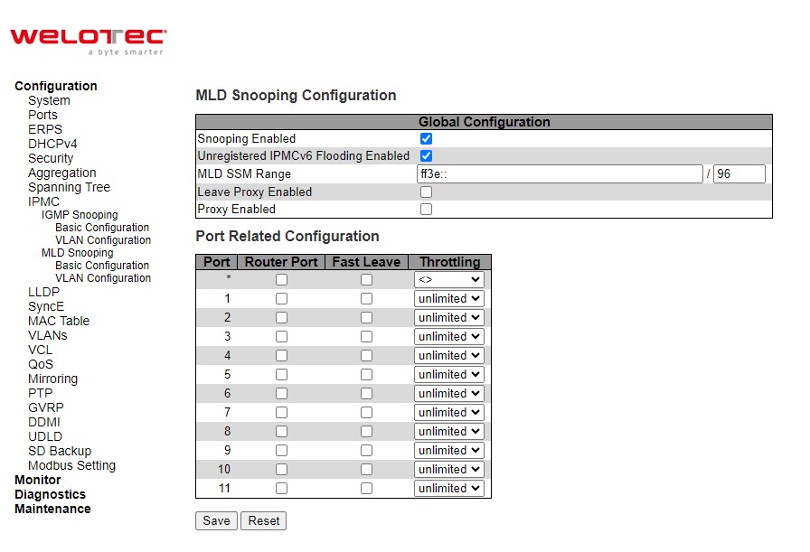
Table 2.67 Descriptions of MLD Snooping Configuration for an IPMC Profile:
Label |
Description |
Factory Default |
|---|---|---|
MLD Snooping Configuration |
||
Snooping Enabled |
Enable the Global MLD Snooping. |
Clicked |
Unregistered IPMCv6 Flooding Enabled |
Enable unregistered IPMCv6 traffic flooding. The flooding control takes effect only when MLD Snooping is enabled. When MLD Snooping is disabled, unregistered IPMCv6 traffic flooding is always active in spite of this settin |
Clicked |
MLD SSM Range |
SSM (Source-Specific Multicast) Range allows the SSM-aware hosts and routers run the SSM service model for the groups in the address range. Assign valid IPv6 multicast address as prefix with a prefix length (from 8 to 128) for the range. |
ff3e::/96 |
Leave Proxy Enabled |
Enable MLD Leave Proxy. This feature can be used to avoid forwarding unnecessary leave messages to the router side. |
Unclicked |
Proxy Enabled |
Enable MLD Proxy. This feature can be used to avoid forwarding unnecessary join and leave messages to the router side. |
Unclicked |
Port Related Configuration |
||
Router Port |
Specify which ports act as router ports. A router port is a port on the Ethernet switch that leads towards the Layer 3 multicast device or MLD querier. If an aggregation member port is selected as a router port, the whole aggregation will act as a router port. |
Unclicked |
Fast Leave |
Enable the fast leave on the port. System will remove group record and stop forwarding data upon receiving the MLDv1 leave message without sending last member query messages. It is recommended to enable this feature only when a single MLDv1 host is connected to the specific port. |
Unclicked |
Throttling |
Enable to limit the number of multicast groups to which a switch port can belong. |
unlimited |
Click Save button to save changes. Click Reset button to undo any changes made locally and revert to previously saved values.
VLAN Configuration
MLD Snooping VLAN Configuration is shown in Figure 2.83. Note that the user needs to enter IP configuration page (System⭢IP⭢Add IP interface) to setup IP interface first before the creation of MLD VLAN interface. The MLD Snooping VLAN table is also displayed on this webpage. Each page can show up to 99 entries from the VLAN table, default being 20, selected through the “entries per page” input field. When first visited, the web page will show the first 20 entries from the beginning of the VLAN Table. The first displayed will be the one with the lowest [VLAN ID] found in the VLAN Table. The “VLAN” input fields allow the user to select the starting point in the VLAN Table. Clicking the Refresh button will update the displayed table starting from that or the next closest VLAN Table match. The >> will use the last entry of the currently displayed entry as a basis for the next lookup. When the end is reached the text “No more entries” is shown in the displayed table. Use the |<< arrow button to start over. Table 2.68 summarizes the descriptions of the MLD Snooping VLAN Configuration.
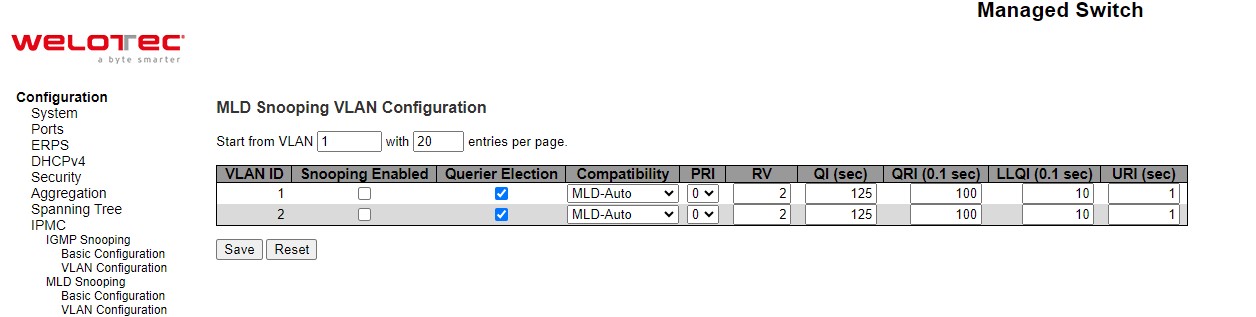
Table 2.68 Descriptions of MLD Snooping’s VLAN Configuration for an IPMC Profile:
Label |
Description |
Factory Default |
|---|---|---|
VLAN ID |
The VLAN ID of the entry. |
1 |
MLD Snooping Enabled |
Enable the per-VLAN IGMP Snooping. Up to 8 VLANs can be selected for MLD Snooping. |
Unclicked |
Querier Election |
Enable to join MLD Querier election in the VLAN. Disable to act as an MLD Non-Querier. |
Clicked |
Compatibility |
Compatibility is maintained by hosts and routers taking appropriate actions depending on the versions of MLD operating on hosts and routers within a network. The allowed selection is MLD-Auto, Forced MLDv1, Forced MLDv2, default compatibility value is MLD-Auto. |
MLD-Auto |
PRI |
Priority of Interface. It indicates the MLD control frame priority level generated by the system. These values can be used to prioritize different classes of traffic. The allowed range is 0 (best effort) to 7 (highest), default interface priority value is 0. |
0 |
RV |
Robustness Variable. The Robustness Variable allows tuning for the expected packet loss on a link. The allowed range is 1 to 255, default robustness variable value is 2. |
2 |
QI (sec) |
Query Interval. The Query Interval is the interval between General Queries sent by the Querier. The allowed range is 1 to 31744 seconds. Default query interval is 125 seconds. |
125 |
QRI (0.1 sec) |
Query Response Interval. The Maximum Response Delay used to calculate the Maximum Response Code inserted into the periodic General Queries. The allowed range is 0 to 31744 in tenths of seconds. Default query response interval is 100 in tenths of seconds (10 seconds). |
100 |
LLQI (0.1 sec) |
Last Listener Query Interval. The Last Listener Query Interval is the Maximum Response Delay used to calculate the Maximum Response Code inserted into Multicast Address Specific Queries sent in response to Version 1 Multicast Listener Done messages. It is also the Maximum Response Delay used to calculate the Maximum Response Code inserted into Multicast Address and Source Specific Query messages. The allowed range is 0 to 31744 in tenths of seconds. Default last listener query interval is 10 in tenths of seconds (1 second). |
10 |
URI (sec) |
Unsolicited Report Interval. The Unsolicited Report Interval is the time between repetitions of a node’s initial report of interest in a multicast address. The allowed range is 0 to 31744 seconds. Default unsolicited report interval is 1 second. |
1 |
Click Refreshes button to refresh the displayed table starting from the “VLAN” input fields. Click |<< button to update the table starting from the first entry in the VLAN Table, i.e., the entry with the lowest VLAN ID. Click >> button to update the table, starting with the entry after the last entry currently displayed. Click Save button to save changes. Click Reset button to undo any changes made locally and revert to previously saved values.
LLDP
Link Layer Discovery Protocol (LLDP) is an IEEE802.1ab standard OSI layer-2 protocol. LLDP allows Ethernet network devices to advertise details about themselves, such as device configuration, capabilities and identification. The advertise packets are periodically sent to directly connected devices on the network that are also using LLDP or so called its neighbours. LLDP is a “one hop” unidirectional protocol in an advertising mode.
LLDP information can only be sent to and received by devices, no solicit information or state changes between nodes. The device has a choice to turn on and off sending and receiving function independently. Advertised information is not forward on to other devices on the network. LLDP is designed to be managed with SNMP. Applications that use this protocol include topology discovery, inventory management, emergency services, VLAN assignment, and inline power supply.
LLDP
The LLDP webpage allows the user to inspect and configure the current LLDP interface settings as shown in Figure 2.84. The page consists of LLDP Parameters and LLDP Interface Configuration. Table 2.69 summarizes the descriptions of the LLDP Configuration.
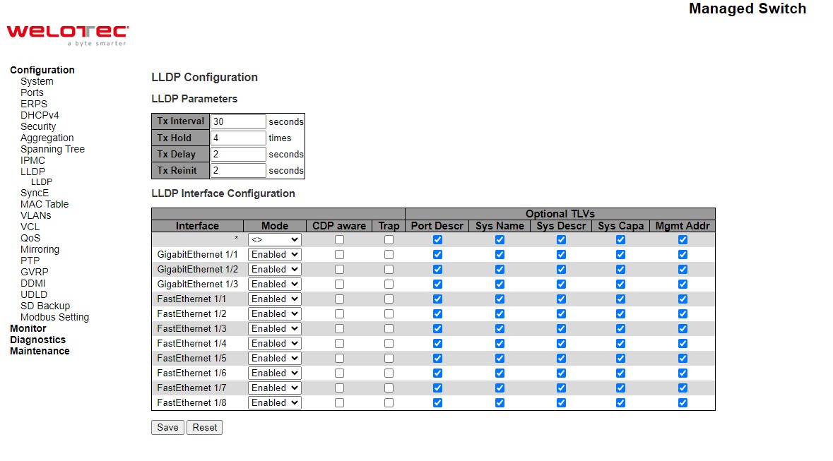
Table 2.69 Descriptions of LLDP Configuration:
Label |
Description |
Factory Default |
|---|---|---|
LLDP Parameters |
||
Tx Interval |
The switch periodically transmits LLDP frames to its neighbours for having the network discovery information up-to-date. The interval between each LLDP frame is determined by the Tx Interval value. Valid values are restricted to 5 - 32768 seconds. |
30 |
Tx Hold |
Each LLDP frame contains information about how long time the information in the LLDP frame shall be considered valid. The LLDP information valid period is set to Tx Hold multiplied by Tx Interval seconds. Valid values are restricted to 2 - 10 times. |
4 |
Tx Delay |
If some configuration is changed (e.g. the IP address) a new LLDP frame is transmitted, but the time between the LLDP frames will always be at least the value of Tx Delay seconds. Tx Delay cannot be larger than 1/4 of the Tx Interval value. Valid values are restricted to 1 - 8192 seconds. |
2 |
Tx Reinit |
When an interface is disabled, LLDP is disabled or the switch is rebooted, a LLDP shutdown frame is transmitted to the neighbouring units, signalling that the LLDP information isn’t valid anymore. Tx Reinit controls the number of seconds between the shutdown frame and a new LLDP initialization. Valid values are restricted to 1 - 10 seconds. |
2 |
LLDP Interface Configuration |
||
Interface |
The switch interface name of the logical LLDP interface. |
GigabitEthernet or FastEthernet |
Mode |
Select LLDP mode. Rx only: The switch will not send out LLDP information, but LLDP information from neighbour units is analysed. Tx only: The switch will drop LLDP information received from neighbours, but will send out LLDP information. Disabled: The switch will not send out LLDP information, and will drop LLDP information received from neighbours. Enabled: The switch will send out LLDP information, and will analyse LLDP information received from neighbours. |
Disabled |
CDP Aware |
Select CDP awareness. The CDP operation is restricted to decoding incoming CDP frames (The switch doesn’t transmit CDP frames). CDP frames are only decoded if LLDP on the interface is enabled. Only CDP TLVs that can be mapped to a corresponding field in the LLDP neighbours’ table are decoded. All other TLVs are discarded (Unrecognized CDP TLVs and discarded CDP frames are not shown in the LLDP statistics.). CDP TLVs are mapped onto LLDP neighbours’ table as shown below. CDP TLV “Device ID” is mapped to the LLDP “Chassis ID” field. CDP TLV “Address” is mapped to the LLDP “Management Address” field. The CDP address TLV can contain multiple addresses, but only the first address is shown in the LLDP neighbours table. CDP TLV “Port ID” is mapped to the LLDP “Port ID” field. CDP TLV “Version and Platform” is mapped to the LLDP “System Description” field. Both the CDP and LLDP support “system capabilities”, but the CDP capabilities cover capabilities that are not part of the LLDP. These capabilities are shown as “others” in the LLDP neighbours’ table. If all interfaces have CDP awareness disabled the switch forwards CDP frames received from neighbour devices. If at least one interface has CDP awareness enabled all CDP frames are terminated by the switch. Note: When CDP awareness on an interface is disabled the CDP information isn’t removed immediately, but gets removed when the hold time is exceeded. |
Unclicked |
Port Descr |
Optional TLV: When checked the “port description” is included in LLDP information transmitted. |
Unclicked |
Sys Name |
Optional TLV: When checked the “system name” is included in LLDP information transmitted. |
Clicked |
Sys Descr |
Optional TLV: When checked the “system description” is included in LLDP information transmitted. |
Clicked |
Sys Capa |
Optional TLV: When checked the “system capability” is included in LLDP information transmitted. |
Clicked |
Mgmt Addr |
Optional TLV: When checked the “management address” is included in LLDP information transmitted. |
Clicked |
Click Save button to save changes. Click Reset button to undo any changes made locally and revert to previously saved values.
SyncE
Synchronous Ethernet (SyncE) uses a physical layer interface to pass timing from one node to the other in the same manner as timing is passed in SONET or SDH. SyncE, as defined by ITU-T standards, such as G.8261, G.8262, G.8264, and G.781, leverages the physical layer of Ethernet to transmit frequency to remote sites. This synchronous transmission of frequency over Ethernet provides a cost-effective alternative for network designers. This functionality is used to make a network ‘clock frequency synchronized’. For SyncE to work, each network element along the synchronization path must support SyncE. Network elements use synchronization status messages (SSM) to inform the neighbouring elements about the quality level (QL) of the clock. SSM is used by non-Ethernet interfaces, such as the optical interfaces and the SONET/T1/E1 SPA framers. SSM functionality provides the following key benefits.
Prevents timing loops
Provides fast recovery when a part of the network fails
Ensures that a node derives timing from the most reliable clock source
To maintain a logical communication channel in synchronous network connections, Ethernet relies on a channel called the Ethernet synchronization messaging channel (ESMC), based on IEEE 802.3 organization-specific slow protocol standards. ESMC relays the SSM code that represents the quality level of the Ethernet equipment clock (EEC) in a physical layer.
The ESMC packets are received only for those ports configured as clock sources and transmitted on all SyncE interfaces in the system. These packets are then processed by the clock selection algorithm and used to select the best clock. The transmitted frame is generated based on the QL value of the selected clock source and sent to all the enabled SyncE ports.
The clock selection algorithm selects the best available synchronization source from the nominated sources. The clock selection algorithm has a non-revertive bRSAESaviour among clock sources with the same QL value and priority. It always selects the signal with the best QL value. The following parameters contribute to the selection process.
Quality level
Signal fail (QL-FAILED)
Priority
External commands (manual, auto-revertive, and so on)
Figure 2.85 illustrates the SyncE Configuration webpage. There are five parts on this webpage which are Clock Source Nomination and State, Clock Selection Mode and State, Station Clock Configuration and Clock hardware, SyncE Ports, and PTP Ports (8265.1).
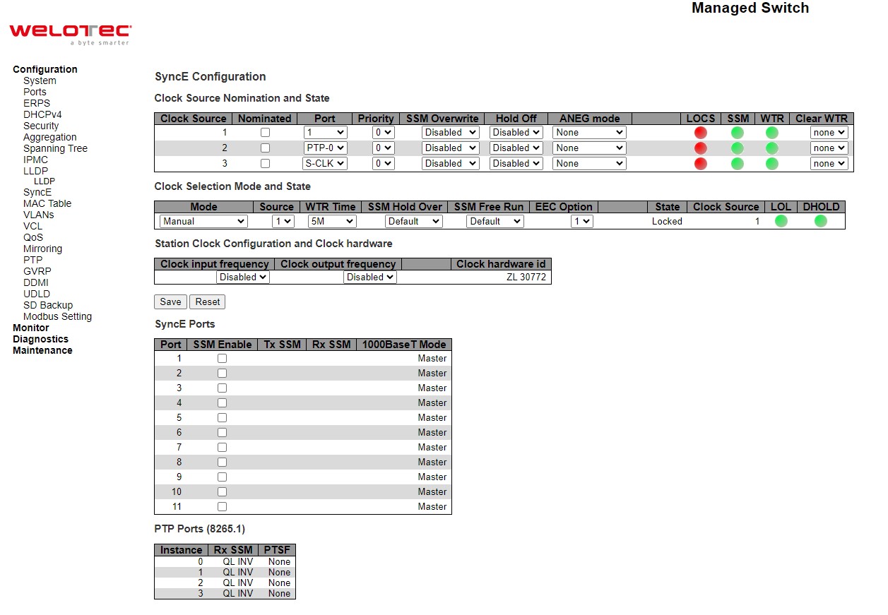
For each possible clock source, the user can configure the parameters under Clock Source Nomination and State part. Table 2.70 summarizes the descriptions of parameters of Clock Source Nomination and State under SyncE.
Table 2.70 Description of Clock Source Nomination and State under SyncE:
Label |
Description |
Factory Default |
|---|---|---|
Clock Source |
This is the instance number of the clock source. This has to be referenced when selecting ‘Manual’ Mode |
- |
Nominated |
When a clock source is nominated, the clock output from the related PHY (Port) is enabled against the clock controller. This makes it available as a possible source in the clock selection process. If it is supported by the actual HW configuration, The Station clock input can be nominated as a Clock Source. |
Unclicked |
Port |
In this dropdown box, the ports that are possible to select for this clock source, is presented. The station clock input is indicated by a port name = ‘S-CLK’. |
- |
Priority |
The priority for this clock source. Lowest number (0) is the highest priority. If two clock sources have the same priority, the lowest clock source number gets the highest priority in the clock selection process. |
0 |
SSM Overwrite |
A selectable clock source Quality Level (QL) to overwrite any QL received in a SSM. If QL is not Received in an SSM (SSM is not enabled on this port), the SSM Overwrite QL is used as if received. The SSM Overwrite can be set to QL_NONE, indicating that the clock source is without any know quality (Lowest compared to clock source with known quality) |
Disabled |
Hold Off |
The Hold Off timer value. Active loss of clock Source will be delayed the selected amount of time. The clock selector will not change clock source if the loss of clock condition is cleared within this time. |
Disabled |
ANEG Mode |
This is relevant for 1000BaseT ports only. In order to recover clock from port it must be negotiated to ‘Slave’ mode. In order to distribute clock, the port must be negotiated to ‘Master’ mode. |
None |
LOCS |
Signal is lost on this clock source. |
- |
SSM |
If SSM is enabled and not received properly. Type of SSM fail will be indicated in the ‘Rx SSM’ field |
- |
WTR |
Wait to Restore timer is active. |
- |
Clear WTR |
Clears the WTR timer and makes this clock source available to the clock selection process. |
None |
For Clock Selection Mode and State, the Clock Selector is only in one instance which is the one who selects between the nominated clock sources. Table 2.71 summarizes the descriptions of parameters of Clock Source Nomination and State under SyncE.
Table 2.71 Description of Clock Selection Mode and State under SyncE:
Label |
Description |
Factory Default |
|---|---|---|
Mode |
The definition of the ‘best’ clock source is firstly the one with the highest (QL) and secondly (the ones with equal QL) the highest priority. |
Auto Revertive |
Source |
Only relevant if Manual mode is selected (see above). |
1 |
WTR Time |
WTR is the Wait-To-Restore timer value in minutes. The WTR time is activated on the falling edge of a clock source failure (in Revertive mode). This means that the clock source is first available for clock selection after WTR Time (can be cleared). |
5M |
SSM Hold Over |
This is the transmitted SSM QL value when clock selector is in Hold Over State. |
Default |
SSM Free Run |
This is the transmitted SSM QL value when clock selector is in Free Run State. |
Default |
EEC Option |
The ZL30xxx based SyncE modules support both EEC1 and EEC2 option. The difference is: EEC1=> DPLL bandwidth=3,5 Hz, EEC2=> DPLL bandwidth = 0,1 Hz. |
1 |
State |
This is indicating the state of the clock selector. Possible states are: |
Free Run |
Clock Source |
The clock source locked to when clock selector is in locked state. |
- |
LOL |
Clock selector has raised the Los Of Lock alarm. |
- |
DHOLD |
Clock selector has not yet calculated the holdover frequency offset to local oscillator. This becomes active for about 10 s. when a new clock source is selected |
- |
The SyncE module may have a station clock input and/or a station clock output. This can be configured under the Station Clock Configuration part.
Table 2.72 Description of Station Clock Configuration under SyncE:
Label |
Description |
Factory Default |
|---|---|---|
Clock input frequency |
If supported by the SyncE HW, the station clock input frequency can be configured, the possible frequencies are: |
Disabled |
Clock output frequency |
If supported by the SyncE HW, the station clock output frequency can be configured, the possible frequencies are: |
Disabled |
Table 2.73 Description of SyncE Ports under SyncE:
Label |
Description |
Factory Default |
|---|---|---|
Port |
The port number to configure. |
- |
SSM Enable |
Enable and disable of SSM functionality on this port. |
Unclicked |
Tx SSM |
Monitoring of the transmitted SSM QL on this port. Transmitted QL should be the Quality Level of the clock generated by this node. This means the QL of the clock source this node is locked to. |
- |
Rx SSM |
Monitoring of the received SSM QL on this port. If link is down on port, QL_LINK is indicated. If no SSM is received, QL_FAIL is indicated. |
- |
1000BaseT Mode |
If PHY is in 1000BaseT Mode then this is monitoring the master/slave mode. In order to receive clock on a port, it has to be in slave mode. In order to transmit clock on a port, it has to be in master mode. |
Master |
Table 2.74 Description of PTP Ports under SyncE:
Label |
Description |
|---|---|
Instance |
The instance number of switch PTP feature |
Rx SSM |
Monitoring of the received SSM QL on this port. If link is down on port, QL_LINK is indicated. If no SSM is received, QL_FAIL is indicated. |
PTSF |
PSFP is an acronym for Per Stream Filtering and Policing. |
Click Refresh button to refresh the page immediately. Click Save button to save changes. Click Reset button to undo any changes made locally and revert to previously saved values.
MAC Table
Unicast and Multicast MAC addresses in the memory, which is the MAC Address Table, of the managed switch can be configured in this webpage as shown in Figure 2.86. The user can set timeouts for entries (called ageing time) in the dynamic MAC Table and configure the static MAC table. The MAC Address Table Configuration webpage consists of four parts: Aging Configuration, MAC Table Learning, VLAN Learning Configuration, and Static MAC Table Configuration.
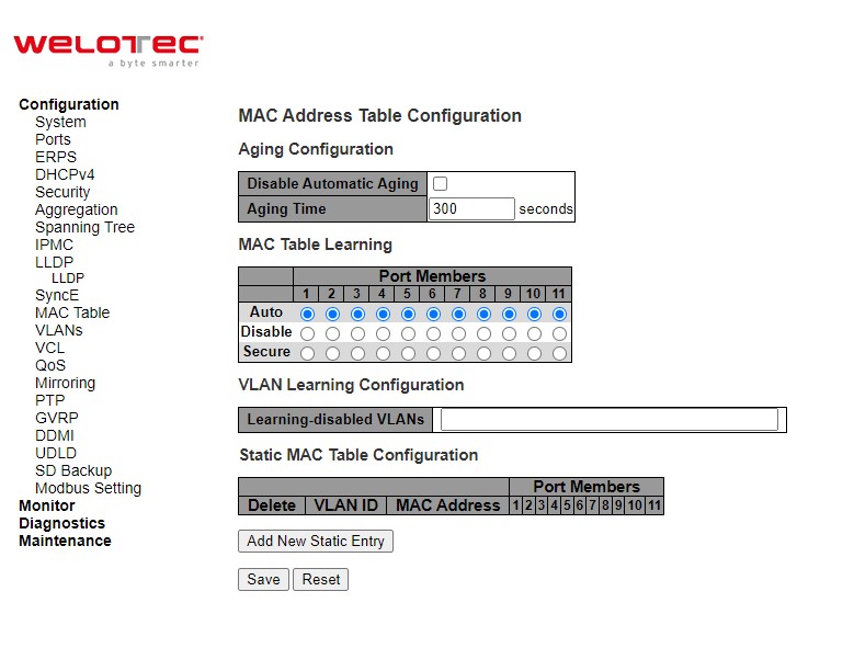
Table 2.75 Description of MAC Address Table Configuration:
Label |
Description |
Factory Default |
|---|---|---|
Aging Configuration |
||
Disable Automatic Aging |
Disable the automatic aging of dynamic entries by checking the box. |
Unclicked |
Aging time |
Configure aging time by entering a value in this field in unit of seconds. The allowed range is 10 to 1000000 seconds. By default, dynamic entries are removed from the MAC Table after 300 seconds. This removal is also called aging. |
300 |
MAC Table Learning |
||
Auto |
Learning is done automatically as soon as a frame with unknown SMAC is received. |
- |
Disable |
No learning is done. |
- |
Secure |
Only static MAC entries are learned, all other frames are dropped. |
- |
VLAN Learning Configuration |
||
Learning-disabled VLANs |
This field shows the Learning-disabled VLANs. When a NEW MAC arrives into a learning-disabled VLAN, the MAC won’t be learnt. By the default, the field is empty. More VLANs may be created by using a list syntax where the individual elements are separated by commas. Ranges are specified with a dash separating the lower and upper bound. |
Null |
Static MAC Table Configuration |
||
Delete |
Check to delete the entry. It will be deleted during the next save. |
- |
VLAN ID |
The VLAN ID of the entry. |
- |
MAC Address |
The MAC address of the entry. |
- |
Port Members |
Checkmarks indicate which ports are members of the entry. Check or uncheck as needed to modify the entry. |
- |
Adding a New Static Entry |
Click Add New Static Entry button to add a new entry to the static MAC table. Specify the VLAN ID, MAC address, and port members for the new entry. Click “Save”. |
- |
Click Save button to save changes. Click Reset button to undo any changes made locally and revert to previously saved values.
VLANs
VLAN or Virtual LAN is a method to restrict communication between switch ports. At layer 2, the network is partitioned into multiple, distinct, mutually isolated broadcast domains. A Virtual Local Area Network (VLAN) is a group of devices that can be located anywhere on a network, but all devices in the group are logically connected together. In other words, VLAN allows end stations to be grouped together even if they are not located on the same network switch. With a traditional network, users usually spend a lot of time on devices relocations, but a VLAN reconfiguration can be performed entirely through software. Also, VLAN provides extra security because devices within a VLAN group can only communicate with other devices in the same group. For the same reason, VLAN can help to control network traffic. Traditional network broadcasts data to all devices, no matter whether they need it or not. By allowing a member to receive data only from other members in the same VLAN group, VLAN avoids broadcasting and increases traffic efficiency (see Figure 2.87).
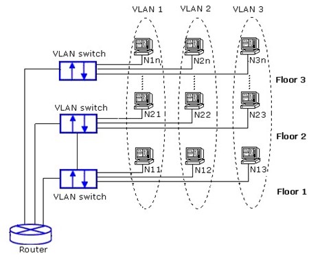
Configuration
VLAN⭢Configuration webpage allows the user to control VLAN configuration on the switch. The page is divided into a global section and a per-port configuration section as shown in
Figure 2.88. Table 2.76 and Table 2.77 provide descriptions of the options on Global VLAN Configuration and Port VLAN Configuration, respectively.
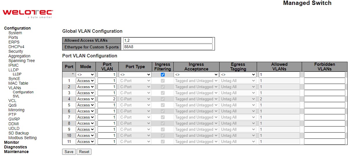
Table 2.76 Description of Global VLAN Configuration:
Label |
Description |
Factory Default |
|---|---|---|
Allowed Access VLANs |
This field shows the allowed Access VLANs, i.e. it only affects ports configured as Access ports. Ports in other modes are members of the VLANs specified in the Allowed VLANs field. By default, only VLAN 1 is enabled. More VLANs may be created by using a list syntax where the individual elements are separated by commas. Ranges are specified with a dash separating the lower and upper bound. The following example will create VLANs 1, 10, 11, 12, 13, 200, and 300: 1,1013,200,300. Spaces are allowed in between the delimiters. |
1 |
Ethertype for Custom S-ports |
This field specifies the ethertype/TPID (specified in hexadecimal) used for Custom S-ports. The setting is in force for all ports whose Port Type is set to S-Custom-Port. |
88A8 |
Table 2.77 Description of Port VLAN Configuration:
Label |
Description |
Factory Default |
|---|---|---|
Port |
This is the logical port number of this row. |
- |
Mode |
The port mode (default is Access) determines the fundamental behaviour of the port in question. A port can be in one of three modes as described below. Whenever a particular mode is selected, the remaining fields in that row will be either greyed out or made changeable depending on the mode in question. Greyed out fields show the value that the port will get when the mode is applied.
Trunk ports can carry traffic on multiple VLANs simultaneously, and are normally used to connect to other switches. Trunk ports have the following characteristics:
Hybrid ports resemble trunk ports in many ways, but adds additional port configuration features. In addition to the characteristics described for trunk ports, hybrid ports have these abilities:
|
Access |
Port VLAN |
Determines the port’s VLAN ID (a.k.a. PVID). Allowed VLANs are in the range 1 through 4095, default being 1. |
- |
Port Type |
Ports in hybrid mode allow for changing the port type, that is, whether a frame’s VLAN tag is used to classify the frame on ingress to a particular VLAN, and if so, which TPID it reacts on. Likewise, on egress, the Port Type determines the TPID of the tag, if a tag is required. |
C-Port |
Ingress Filtering |
Hybrid ports allow for changing ingress filtering. Access and Trunk ports always have ingress filtering enabled. |
Unclicked |
Ingress Acceptance |
Hybrid ports allow for changing the type of frames that are accepted on ingress. |
Tagged and Untagged |
Egress Tagging |
Ports in Trunk and Hybrid mode may control the tagging of frames on egress. |
Untag All |
Allowed VLANs |
Ports in Trunk and Hybrid mode may control which VLANs they are allowed to become members of. Access ports can only be member of one VLAN, the Access VLAN. The field’s syntax is identical to the syntax used in the Enabled VLANs field. By default, a Trunk or Hybrid port will become member of all VLANs, and is therefore set to 1-4095. The field may be left empty, which means that the port will not become member of any VLANs. |
1 |
Forbidden VLANs |
A port may be configured to never become member of one or more VLANs. This is particularly useful when dynamic VLAN protocols like MVRP and GVRP must be prevented from dynamically adding ports to VLANs. |
Null |
Click Save button to save changes. Click Reset button to undo any changes made locally and revert to previously saved values.
SVL
SVL or Shared VLAN Learning Configuration can be set on the managed switch through this webpage as shown in Figure 2.89. In SVL, one or more VLANs map to a Filter ID (FID). By default, there is a one-to-one mapping from VLAN to FID, in which case the switch acts as an IVL (Independent VLAN Learning) bridge, but with SVL multiple VLANs may share the same MAC address table entries. Click Add FID button to add a new row to the SVL table. The FID will be pre-filled with the first unused FID. Table 2.78 summarizes the descriptions of Shared VLAN Learning Configuration.
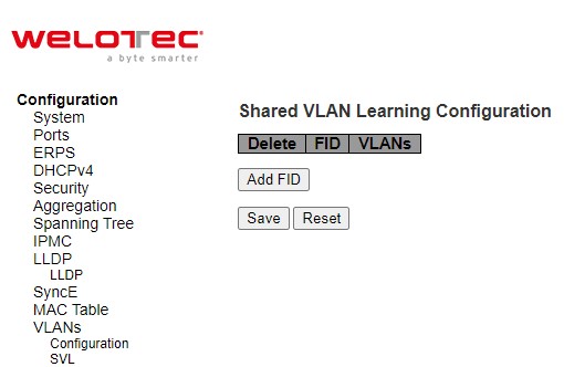
Table 2.78 Description of Shared VLAN Learning Configuration:
Label |
Description |
Factory Default |
|---|---|---|
Delete |
A previously allocated FID can be deleted by the use of this button. |
- |
FID |
The Filter ID (FID) is the ID that VLANs get learned on in the MAC table when SVL is in effect. No two rows in the table can have the same FID and the FID must be a number between 1 and 63. |
1 |
VLANs |
List of VLANs mapped into FID. |
- |
Click Save button to save changes. Click Reset button to undo any changes made locally and revert to previously saved values.
VCL
MAC-based VLAN
The MAC address to VLAN ID mappings can be configured in Figure 2.90. This page allows adding and deleting MACbased VLAN Classification List entries and assigning the entries to different ports. Figure 2.77 summarizes the descriptions of MAC-based VLAN Membership Configuration.
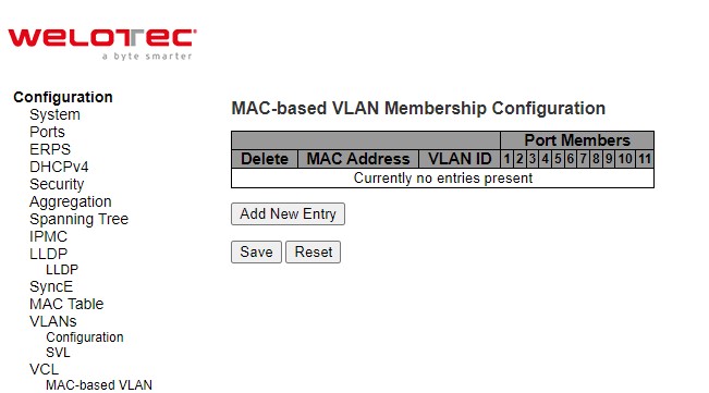
Table 2.79 Descriptions of MAC-based VLAN Configuration of VCL:
Label |
Description |
Factory Default |
|---|---|---|
Delete |
To delete a MAC to VLAN ID mapping entry, check this box and press save. The entry will be deleted in the stack. |
- |
MAC Address |
Indicates the MAC address of the mapping. |
00-00-00-00-00-00 |
VLAN ID |
Indicates the VLAN ID the above MAC will be mapped to. |
1 |
Port Numbers |
A row of check boxes for each port is displayed for each MAC to VLAN ID mapping entry. To include a port in the mapping, check the box. To remove or exclude the port from the mapping, make sure the box is unchecked. By default, no ports are members, and all boxes are unchecked. |
- |
Click Add New Entry button to add a new MAC to VLAN ID mapping entry. An empty row is added to the table, and the mapping can be configured as needed. Any unicast MAC address can be used to configure the mapping. No broadcast or multicast MAC addresses are allowed. Legal values for a VLAN ID are 1 through 4095. The MAC to VLAN ID entry is enabled when you click on “Save” button. A mapping without any port members will not be added when you click “Save” button. The Delete button can be used to undo the addition of new mappings. The maximum possible MAC to VLAN ID mapping entries is limited to 256.
Click Save button to save the setting configuration. Click Reset button to keep to the original setting.
Protocol-based VLAN
Protocol to Group
Figure 2.91 is the webpage that allows you to add new Protocol to Group Name mapping entries. Note that each protocol can be part of only one Group. It also allows you to see and delete current mapped entries for the switch. Table 2.80 provides the descriptions of the Protocol to Group Mapping Table.
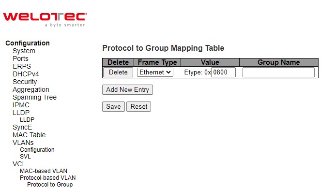
Table 2.80 Descriptions of Protocol to Group Mapping Table Configuration
Label |
Description |
Factory Default |
|---|---|---|
Delete |
To delete a Protocol to Group Name map entry, check this box. The entry will be deleted from the switch during the next Save. |
- |
Frame Type |
Frame Type can have one of the following values:
|
Ethernet |
Value |
Valid value that can be entered in this text field depends on the option selected from the preceding Frame Type selection menu. Below are the criteria for the three different Frame Types:
|
0x0800 |
Group Name |
A valid Group Name is a 16-character long string, unique for every entry, which consists of a combination of alphabets (a-z or A-Z) and integers (0-9). |
- |
Click Add New Entry button to add a new entry in the mapping table. An empty row is added to the table, where Frame Type, Value and the Group Name can be configured as needed. The Delete button can be used to undo the addition of new entry. The maximum possible Protocol to Group mappings is limited to 128. Click Save button to save the setting configuration. Click Reset button to keep to the original setting.
Group to VLAN
This page allows the user to map a Group Name, which is already configured or going to be configured in the future, to a VLAN for the managed switch. Figure 2.92 shows the Group Name to VLAN mapping Table. Description of each column’s label can be found in Table 2.81.
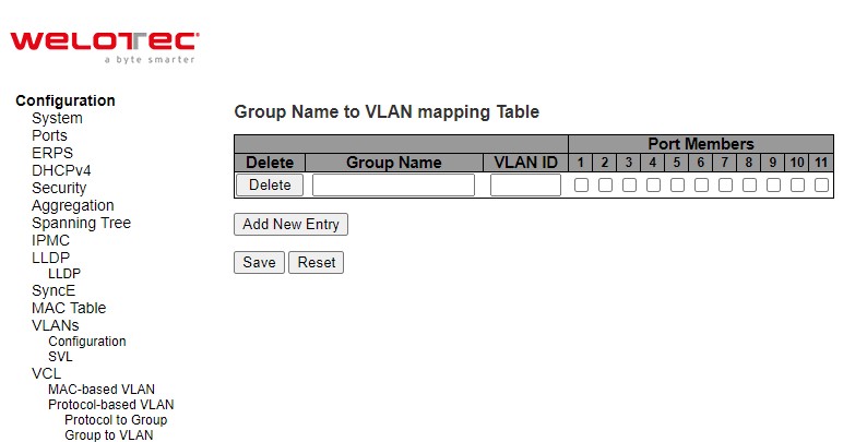
Table 2.81 Descriptions of Group name to VLAN Mapping Table Configuration:
Label |
Description |
Factory Default |
|---|---|---|
Delete |
To delete a Group Name to VLAN mapping, check this box. The entry will be deleted from the switch during the next Save. |
- |
Group Name |
A valid Group Name is a string, at the most 16 characters long, which consists of a combination of alphabets (a-z or A-Z) and integers (0-9) with no special characters allowed. You may either use a Group that already includes one or more protocols (see Protocol to Group mappings), or create a Group to VLAN ID mapping that will become active the moment you add one or more protocols inside that Group. Furthermore, the Group to VLAN ID mapping is not unique, as long as the port lists of these mappings are mutually exclusive (e.g., Group1 can be mapped to VID 1 on port#1 and to VID 2 on port#2). |
Null |
VLAN ID |
Indicates the VLAN ID to which the Group Name will be mapped. A valid VLAN ID ranges from 1 to 4095. |
Null |
Port Members |
A row of check boxes for each port is displayed for each Group Name to VLAN ID mapping. To include a port in the mapping, check the box. To remove or exclude the port from the mapping, make sure the box is unchecked. By default, no ports are members, and all boxes are unchecked. |
Unclicked |
Click Add New Entry button to add a new entry in the mapping table. An empty row is added to the table and the Group Name, VLAN ID and port members can be configured as needed. Legal values for a VLAN ID are 1 through 4095. The Delete button can be used to undo the addition of new entry. The maximum possible Groups to VLAN mappings are limited to 256. Click Save button to save the setting configuration. Click Reset button to keep to the original setting.
IP Subnet-based VLAN
The IP subnet to VLAN ID mappings can be configured on the webpage as shown in Figure 2.93. This page allows adding, updating and deleting IP subnet to VLAN ID mapping entries and assigning them to different ports. Table 2.82 describes the column’s label in the IP Subnet-based VLAN membership configuration.
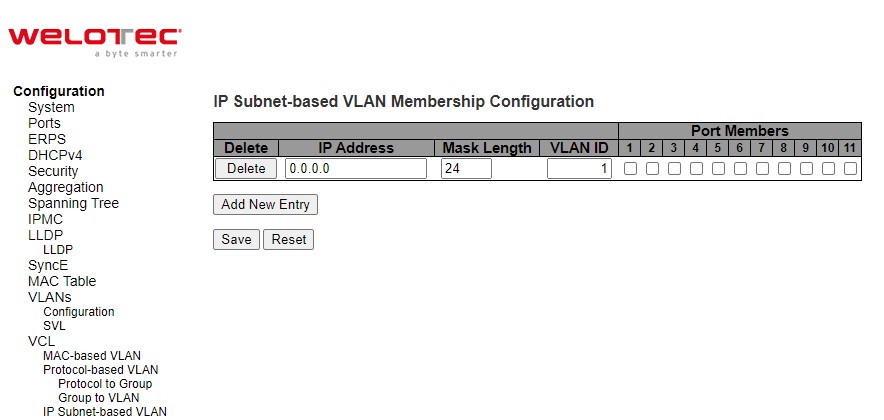
Table 2.82 Descriptions of IP Subnet-based VLAN Configuration_
Label |
Description |
Factory Default |
|---|---|---|
Delete |
To delete a mapping, check this box and press save. The entry will be deleted in the stack. |
- |
IP Address |
Indicates the subnet’s IP address (Any of the subnet’s host addresses can be also provided here, the application will convert it automatically). |
0.0.0.0 |
Mask Length |
Indicates the subnet’s mask length. |
24 |
VLAN ID |
Indicates the VLAN ID the subnet will be mapped to. IP Subnet to VLAN ID is a unique matching. |
1 |
Port Members |
A row of check boxes for each port is displayed for each IP subnet to VLAN ID mapping entry. To include a port in a mapping, simply check the box. To remove or exclude the port from the mapping, make sure the box is unchecked. By default, no ports are members and all boxes are unchecked. |
Unclicked |
Click Add New Entry to add a new IP subnet to VLAN ID mapping entry. An empty row is added to the table, and the mapping can be configured as needed. Any IP address/mask can be configured for the mapping. Valid values for the VLAN ID are 1 to 4095. The IP subnet to VLAN ID mapping entry is enabled when you click on “Save” button. The Delete button can be used to undo the addition of new mappings. The maximum possible IP subnet to VLAN ID mappings is limited to 128.
Click Save button to save the setting configuration. Click Reset button to keep to the original setting. Check the Auto-refresh box to refresh the page automatically. The automatic refresh occurs every 3 seconds. Otherwise, click Refresh box to refresh the page immediately.
QoS
Quality of Service (QoS) is the ability to provide different priority to different applications, users, or data flows. QoS guarantees a certain level of performance to a data flow by using the following metrics: transmitted bit rate, bit error rate, delay, jitter, and probability of packet dropping. QoS guarantees are important if the network capacity is insufficient, especially for application that requires certain bit rate and is delay sensitive. For any network that is best effort, QoS cannot be guaranteed, except that resource is more than sufficient to serve users.
Controlling network traffic needs a set of rules to help classify different types of traffic and define how each of them should be treated as they are being transmitted. This managed switch can inspect both 802.1p Class of Service (CoS) tags and DiffServ tags called Differentiated Services Code Point (DSCP) to provide consistent classification.
Port Classification
The Port Classification webpage shown in Figure 2.94 allows the user to configure the basic QoS Ingress Classification settings for all of managed switch ports. Table 2.83 provides the descriptions of the setting parameters of QoS Port Classification.
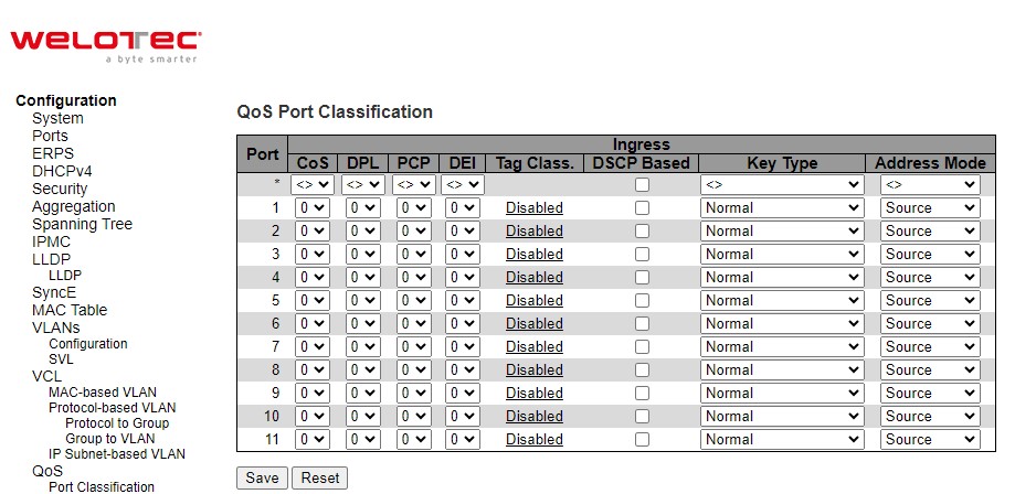
Table 2.83 Descriptions of Port Classification Configuration of QoS:
Label |
Description |
Factory Default |
|---|---|---|
Port |
The port number for which the configuration below applies. |
- |
CoS |
Controls the default class of service (CoS) value. |
0 |
DPL |
Controls the default Drop Precedence Level (DPL) value. All frames are classified to a Drop Precedence Level. If the port is VLAN aware, the frame is tagged and Tag Class. is enabled, then the frame is classified to a DPL that is mapped from the PCP and DEI value in the tag. Otherwise, the frame is classified to the default DPL. The classified DPL can be overruled by a QCL entry. |
0 |
PCP |
Controls the default Priority Code Point (PCP) value. All frames are classified to a PCP value. If the port is VLAN aware and the frame is tagged, then the frame is classified to the PCP value in the tag. Otherwise, the frame is classified to the default PCP value. Note: PCP is a 3-bit field storing the priority level for the 802.1Q frame. It is also known as User Priority. |
0 |
DEI |
Controls the default Drop Eligible Indicator (DEI) value. It is a 1-bit field in the VLAN tag. All frames are classified to a DEI value. If the port is VLAN aware and the frame is tagged, then the frame is classified to the DEI value in the tag. Otherwise, the frame is classified to the default DEI value. |
0 |
Tag Class. |
Shows the classification mode for tagged frames on this port. |
Disabled |
DSCP Based |
Click to Enable Differentiated Services Code Point (DSCP) Based QoS Ingress Port Classification. It is a field in the header of IP packets for packet classification purposes. |
Unclicked |
Key Type |
The key type specifying the key generated for frames received on the port. The allowed values are: |
Normal |
Address Mode |
The IP/MAC address mode specifying whether the QoS Control List (QCL) classification must be based on source (SMAC/SIP) or destination (DMAC/DIP) addresses on this port. This parameter is only used when the key type is Normal. The allowed values are: Source: Enable SMAC/SIP matching. Destination: Enable DMAC/DIP matching. |
Source |
Click Save button to save the setting configuration. Click Reset button to keep to the original setting.
Port Policing
Port Policing webpage allows the user to configure the Policer settings for all switch ports. Note that a policer can limit the bandwidth of received frames. It is located in front of the ingress queue. QoS Ingress Port Policer Table is shown in Figure 2.95. The descriptions of QoS Ingress Port Policers are explained in Table 2.84.
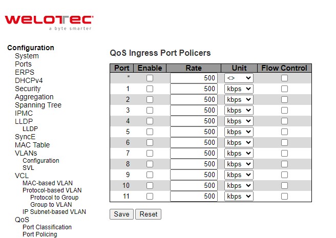
Table 2.84 Descriptions of Port Policing Configuration of QoS:
Label |
Description |
Factory Default |
|---|---|---|
Port |
The port number for which the configuration below applies. |
- |
Enable |
Enable or disable the port policer for this switch port. |
Unchecked |
Label |
Description |
Factory Default |
Rate |
Controls the rate for the port policer. This value is restricted to 100-3276700 when “Unit” is kbps or fps, and 1-3276 when “Unit” is Mbps or kfps. The rate is internally rounded up to the nearest value supported by the port policer. |
500 |
Unit |
Controls the unit of measure for the port policer rate as kbps, Mbps, fps or kfps. |
kbps |
Flow Control |
If flow control is enabled and the port is in flow control mode, then pause frames are sent instead of discarding frames. |
Unchecked |
Click Save button to save the setting configuration. Click Reset button to keep to the original setting.
Queue Policing
To configure the Queue Policer settings for all switch ports, the user can check the corresponding boxes in the table in Figure 2.96. Table 2.85 describes the labels in QoS Ingress Queue Policer Table.
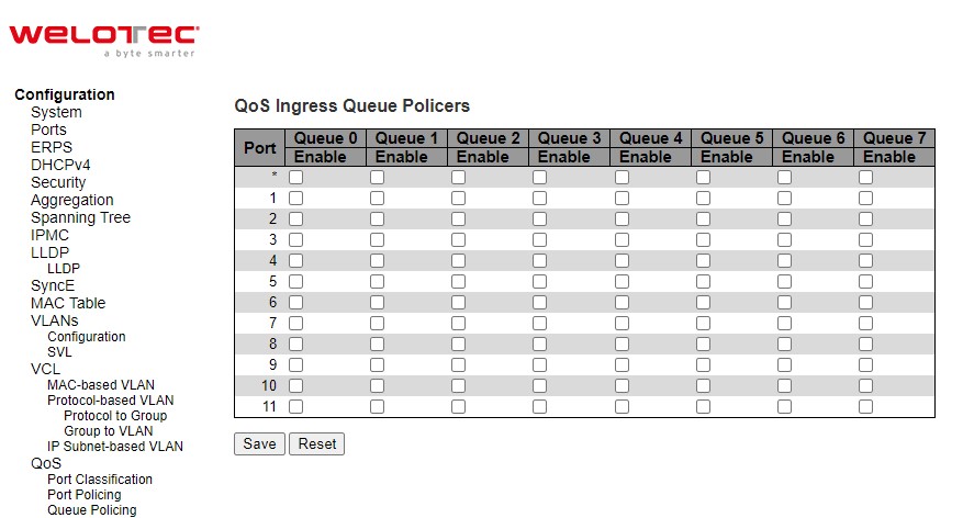
Table 2.85 Descriptions of Queue Policing Configuration of QoS:
Label |
Description |
Factory Default |
|---|---|---|
Port |
The port number for which the configuration below applies. |
- |
Enable (E) |
Enable or disable the port policer for this switch port. |
unchecked |
Rate |
Controls the rate for the port policer. This value is restricted to 100-3276700 when “Unit” is kbps, and 1-3276 when “Unit” is Mbps. The rate is internally rounded up to the nearest value supported by the port policer. This field is only shown if at least one of the queue policers are enabled. |
500 |
Unit |
Controls the unit of measure for the queue policer rate as kbps or Mbps. This field is only shown if at least one of the queue policers are enabled. |
kbps |
Click Save button to save the setting configuration. Click Reset button to keep to the original setting.
Port Scheduler
This webpage provides an overview of QoS Egress Port Schedulers for all switch ports as shown in Figure 2.97. Table 2.86 describes the labels in the QoS Egress Port Schedulers.
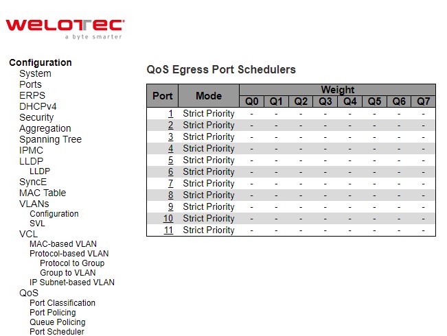
Table 2.86 Descriptions of Port Scheduler Configuration of QoS:
Label |
Description |
Factory Default |
|---|---|---|
Port |
The logical port for the settings contained in the same row. Click on the port number in order to configure the schedulers. |
- |
Mode |
Shows the scheduling mode for this port. |
Strict Priority |
Qn |
Shows the weight for this queue and port. |
- |
After Clicking hyperlink on any port, another webpage configuration will be launched, as shown in Figure 2.98. Table 2.87 describes the QoS Egress Port Scheduler and Shapers Port Configuration.
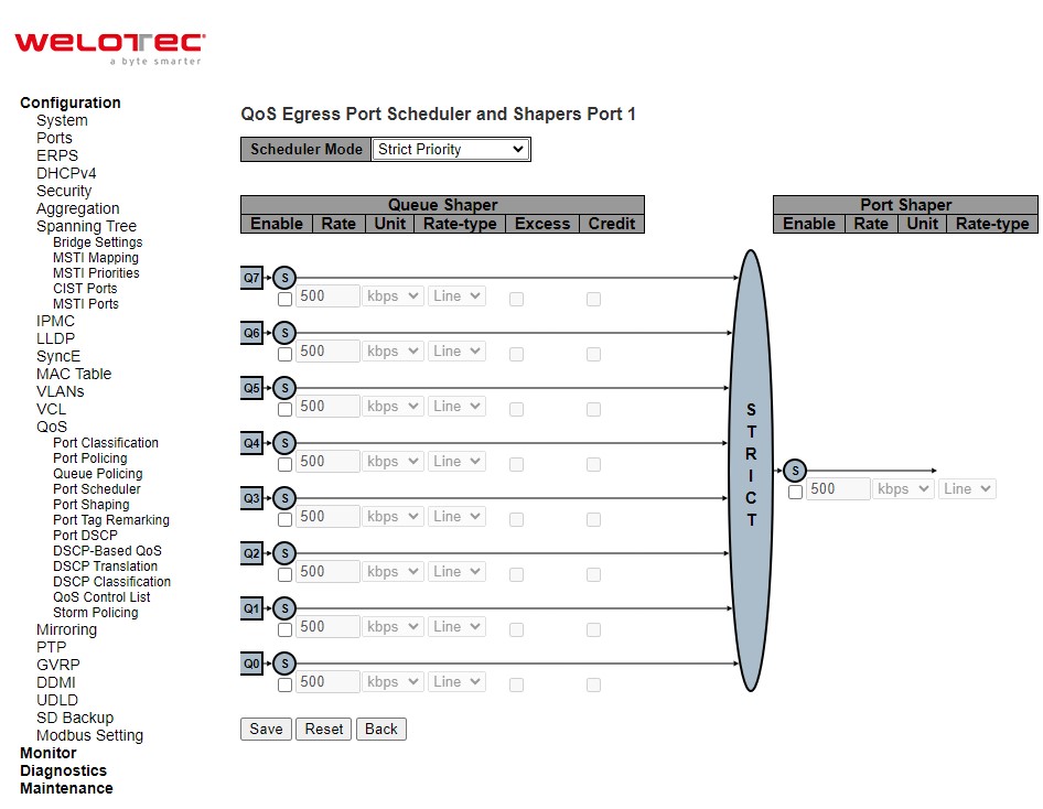
Table 2.87 Descriptions of QoS Egress Port Scheduler and Shapers Port Configuration:
Label |
Description |
Factory Default |
|---|---|---|
Scheduler Mode |
Controls how many of the queues are scheduled as strict and how many are scheduled as weighted on this switch port. |
Strict Priority |
Queue Shaper |
||
Enable |
Controls whether the queue shaper is enabled for this queue on this switch port. |
Unclicked |
Rate |
Controls the rate for the queue shaper. This value is restricted to 1003281943 when “Unit” is kbps, and 1-3281 when “Unit” is Mbps. The rate is internally rounded up to the nearest value supported by the queue shaper. |
500 |
Unit |
Controls the unit of measure for the queue shaper rate as kbps or Mbps. |
Kbps |
Rate-type |
The rate type of the queue shaper. The allowed values are: |
Line |
Excess |
Controls whether the queue is allowed to use excess bandwidth. |
Unclicked |
Credit |
Controls whether the queue has credit-based shaper enabled. |
Unclicked |
Queue Scheduler |
||
Weight |
Controls the weight for this queue. This value is restricted to 1-100. This parameter is only shown if “Scheduler Mode” is set to “Weighted”. |
|
Percent |
Shows the weight in percent for this queue. This parameter is only shown if “Scheduler Mode” is set to “Weighted”. |
|
Port Shaper |
||
Enable |
Controls whether the port shaper is enabled for this switch port. |
Unclicked |
Rate |
Controls the rate for the port shaper. This value is restricted to 100-3281943 when “Unit” is kbps, and 1-3281 when “Unit” is Mbps. The rate is internally rounded up to the nearest value supported by the port shaper. |
500 |
Unit |
Controls the unit of measure for the port shaper rate as kbps or Mbps. |
Kbps |
Rate-type |
The rate type of the port shaper. The allowed values are: |
Line |
Click Save button to save changes. Click Reset button to undo any changes made locally and revert to previously saved values. Click Back button to undo any changes made locally and return to the previous page.
Port Shaping
This webpage provides an overview of QoS Egress Port Shapers for all switch ports as shown in Figure 2.99. Table 2.88 describes the labels in QoS Egress Port Shapers.
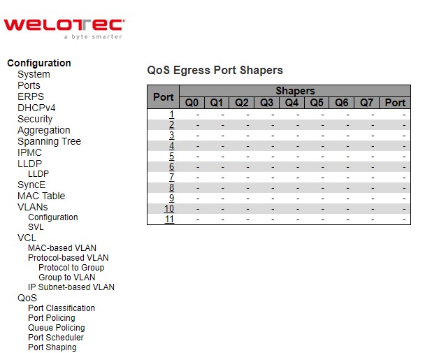
Table 2.88 Descriptions of Port Shaping Configuration of QoS:
Label |
Description |
Factory Default |
|---|---|---|
Port |
The logical port for the settings contained in the same row. Click on the port number in order to configure the shapers. |
- |
Qn |
Shows “-” for disabled or actual queue shaper rate - e.g., “800 Mbps”. |
- |
Port |
Shows “-” for disabled or actual port shaper rate - e.g., “800 Mbps”. |
- |
After Clicking hyperlink on any port, another webpage configuration will be launched, as shown in Figure 2.100. Table 2.89 describes the detaled QoS Egress Port Scheduler and Shapers Port Configuration.
This page allows you to configure the Scheduler and Shapers for a specific port.
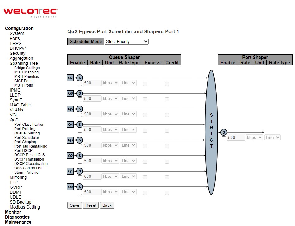
Table 2.89 Descriptions of Detaled QoS Egress Port Scheduler and Shapers Port Configuration:
Label |
Description |
Factory Default |
|---|---|---|
Scheduler Mode |
Controls how many of the queues are scheduled as strict and how many are scheduled as weighted on this switch port. |
Strict Priority |
Queue Shaper |
||
Enable |
Controls whether the queue shaper is enabled for this queue on this switch port. |
Unclicked |
Rate |
Controls the rate for the queue shaper. This value is restricted to 1003281943 when “Unit” is kbps, and 1-3281 when “Unit” is Mbps. The rate is internally rounded up to the nearest value supported by the queue shaper. |
500 |
Unit |
Controls the unit of measure for the queue shaper rate as kbps or Mbps. |
Kbps |
Rate-type |
The rate type of the queue shaper. The allowed values are: |
Line |
Excess |
Controls whether the queue is allowed to use excess bandwidth. |
Unclicked |
Credit |
Controls whether the queue has credit-based shaper enabled. |
Unclicked |
Queue Scheduler |
||
Weight |
Controls the weight for this queue. This value is restricted to 1-100. This parameter is only shown if “Scheduler Mode” is set to “Weighted”. |
|
Percent |
Shows the weight in percent for this queue. This parameter is only shown if “Scheduler Mode” is set to “Weighted”. |
|
Port Shaper |
||
Enable |
Controls whether the port shaper is enabled for this switch port. |
Unclicked |
Rate |
Controls the rate for the port shaper. This value is restricted to 1003281943 when “Unit” is kbps, and 1-3281 when “Unit” is Mbps. The rate is internally rounded up to the nearest value supported by the port shaper. |
500 |
Unit |
Controls the unit of measure for the port shaper rate as kbps or Mbps. |
Kbps |
Rate-type |
The rate type of the port shaper. The allowed values are: |
Line |
Click Save button to save changes. Click Reset button to undo any changes made locally and revert to previously saved values. Click Back button to undo any changes made locally and return to the previous page.
Port Tag Remarking
This webpage provides an overview of QoS Egress Port Tag Remarking for all switch ports as shown in Figure 2.101. Table 2.90 describes the labels in QoS Egress Port Tag Remarking.
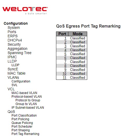
Table 2.90 Descriptions of Port Tag Remarking Configuration of QoS:
Label |
Description |
|---|---|
Port |
The logical port for the settings contained in the same row. Click on the port number in order to configure tag remarking. |
Mode |
Shows the tag remarking mode for this port. Classified: Use classified PCP/DEI values. Default: Use default PCP/DEI values. Mapped: Use mapped versions of QoS class and DP level. |
After clicking into any port, the following webpage will be launched as shown in Figure 2.102. Table 2.901 describes the labels in Each Port Tag Remarking Mode of QoS.
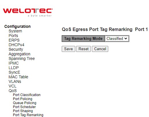
Table 2.91 Descriptions for Port Tag Remarking Configuration of Mode:
Label |
Description |
|---|---|
Mode |
Controls the tag remarking mode for this port. |
Classified |
Use classified PCP/DEI values. |
Default |
Use default PCP/DEI values |
Mapped |
Use mapped versions of CoS and DPL. |
PCP/DEI Configuration |
Controls the default PCP and DEI values used when the mode is set to Default. |
(CoS, DPL) to (PCP, DEI) Mapping |
Controls the mapping of the classified (CoS, DPL) to (PCP, DEI) values when the mode is set to Mapped. |
Port DSCP
The Port DSCP webpage allows the user to configure the basic Quality of Server (QoS) Port Differentiated Service Code Point (DSCP) Configuration settings for all switch ports. The QoS Port DSCP Configuration table is shown in Figure 2.103. The user can change the setting of either or both ingress or egress traffic. Table 2.92 explains the options for each port in QoS Port DSCP Configuration.
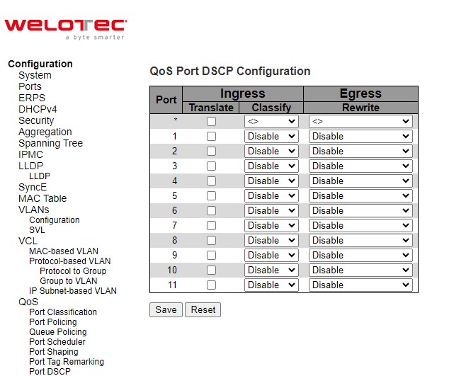
Table 2.92 Descriptions of Port DSCP Configuration of QoS:
Label |
Description |
Factory Default |
|
|---|---|---|---|
Port |
The Port column shows the list of ports for which you can configure DSCP ingress and egress settings. |
- |
|
Ingress |
Translate |
In Ingress settings you can change ingress translation and classification settings for individual ports. There are two configuration parameters available in Ingress: |
Unchecked |
Classify |
2. Classify: Classification for a port have 4 different values.
|
Disable |
|
Egress Rewrite |
Port Egress Rewriting can be one of –
|
Disable |
Click Save button to save the setting configuration. Click Reset button to keep to the original setting.
DSCP-Based QoS
This page as shown in Figure 2.104 allows the user to configure the basic QoS DSCP based QoS Ingress Classification settings for the managed switch. The maximum number of supported DSCP (Differentiated Services Code Point) is 64 as shown in the table. Table 2.93 describes the options for each DSCP.
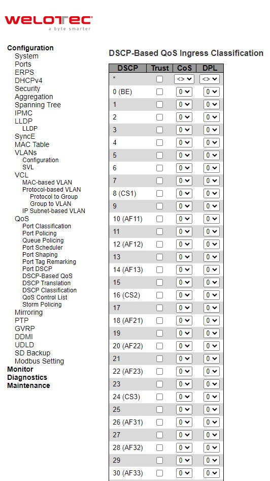
Table 2.93 Descriptions of DSCP-Based Configuration of QoS:
Label |
Description |
Factory Default |
|---|---|---|
DSCP |
Maximum number of supported DSCP values is 64. |
- |
Trust |
Controls whether a specific DSCP value is trusted. Only frames with trusted DSCP values are mapped to a specific QoS class and Drop Precedence Level (DPL). Frames with untrusted DSCP values are treated as a non-IP frame. |
Unchecked |
CoS |
CoS class value can be any of (0-7) |
0 |
DPL |
Drop Precedence Level (0-1) |
0 |
Click Save button to save the setting configuration. Click Reset button to keep to the original setting.
DSCP Translation
DSCP Translation webpage as shown in Figure 2.105 allows you to configure the basic QoS DSCP Translation settings for the managed switch. DSCP translation can be done in Ingress or Egress. Table 2.94 describes the setting options for DSCP Translation.
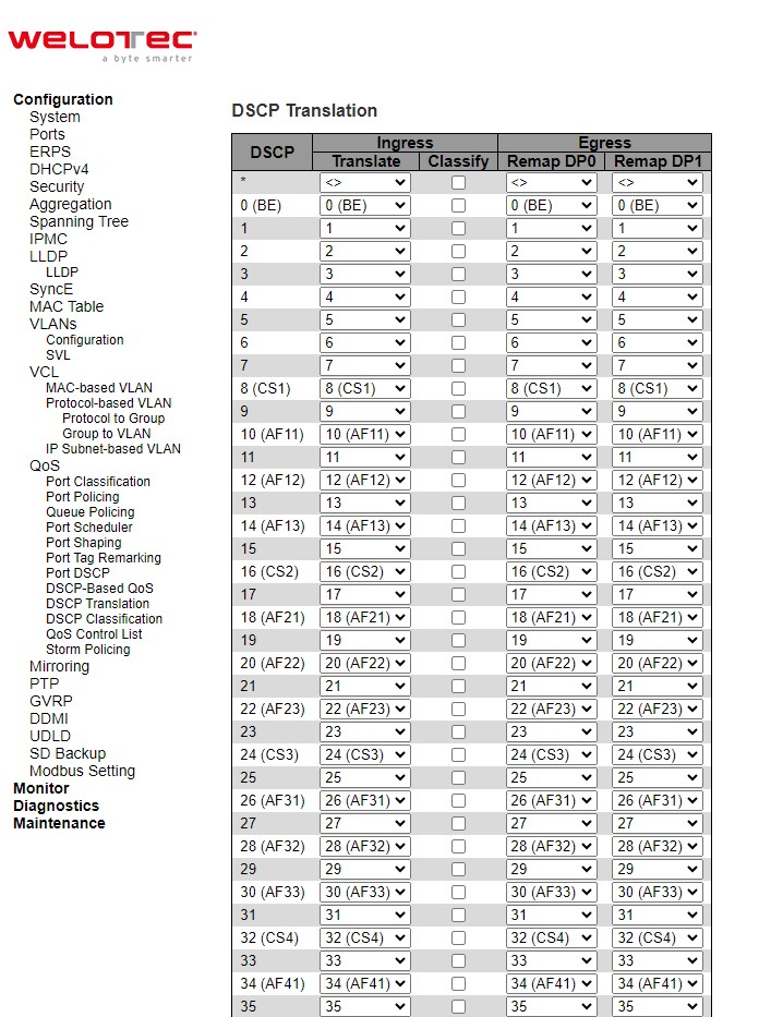
Table 2.94 Descriptions of DSCP Translation Configuration of QoS:
Label |
Description |
Factory Default |
|
|---|---|---|---|
DSCP |
Maximum number of supported DSCP values are 64 and valid DSCP value ranges from 0 to 63. |
- |
|
Ingress |
Translate |
Ingress side DSCP can be first translated to new DSCP before using the DSCP for QoS class and DPL map. |
- |
Classify |
Click to enable Classification at Ingress side. |
Unchecked |
|
Egress |
There are the following configurable parameters for Egress side – |
- |
|
DP0 /DP1 |
Select the DSCP value from select menu to which you want to remap. DSCP value ranges from 0 to 63. |
- |
Click Save button to save the setting configuration. Click Reset button to keep to the original setting.
DSCP Classification
The DSCP Classification webpage as shown in Figure 2.106 allows you to configure the mapping of Class of Service (CoS) or QoS Class and Drop Precedence Level (DPL) to DSCP value. Table 2.95 explains the options for DSCP Classification.
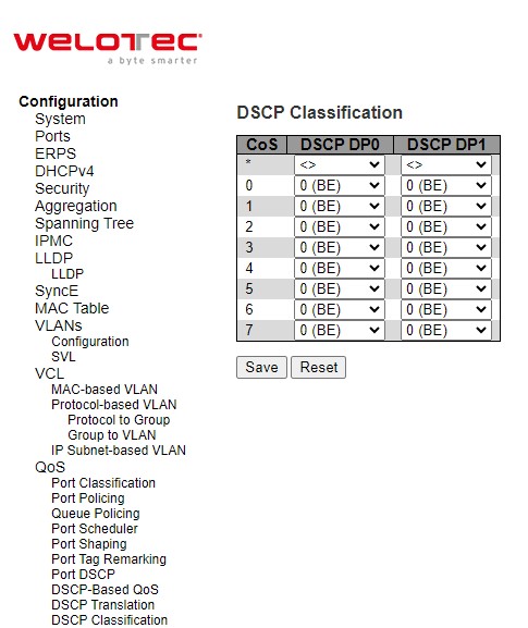
Table 2.95 Descriptions of DSCP Classification Configuration of QoS
Label |
Description |
Factory Default |
|---|---|---|
QoS Class |
Actual QoS class. |
- |
DSCP DP0 |
Select the classified DSCP value (0-63) for Drop Precedence Level 0. |
0 |
DSCP DP1 |
Select the classified DSCP value (0-63) for Drop Precedence Level 1. |
0 |
Click Save button to save the setting configuration. Click Reset button to keep to the original setting.
QoS Control List
The QoS Control List webpage as shown in Figure 2.107 shows the QoS Control List (QCL), which is made up of the QCEs (QoS Control Entries). Each row describes a QCE that is defined. Table 2.96 describes the definition of each column in the list. The maximum number of QCEs is 256 on each switch. To add a new entry, click on the plus sign to add a new QCE to the list and the webpage is updated as shown in Figure 2.108. This updated webpage allows the user to edit or insert one single QoS Control Entry at a time. A QCE consists of several parameters as described in Table 2.97. These parameters vary according to the frame type that the user selected.
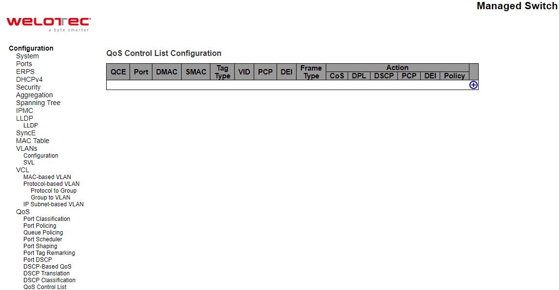
Table 2.96 Descriptions of QoS Control List Configuration:
Label |
Description |
Factory Default |
|---|---|---|
QCE |
Indicates the QCE id. |
- |
Port |
Indicates the list of ports configured with the QCE or ‘Any’. |
- |
DMAC |
Indicates the destination MAC address. Possible values are: |
- |
SMAC |
Match specific source MAC address or ‘Any’. If a port is configured to match on destination addresses, this field indicates the DMAC. |
- |
Tag |
Indicates tag type. Possible values are: |
- |
VID |
Indicates (VLAN ID), either a specific VID or range of VIDs. VID can be in the range 14095 or ‘Any’ |
- |
PCP |
Priority Code Point: Valid values of PCP are specific (0, 1, 2, 3, 4, 5, 6, 7) or range (0-1, 23, 4-5, 6-7, 0-3, 4-7) or ‘Any’. |
- |
DEI |
Drop Eligible Indicator: Valid value of DEI are 0, 1 or ‘Any’. |
- |
Frame Type |
Indicates the type of frame. Possible values are: |
- |
Action Parameters |
Indicates the classification action taken on ingress frame if parameters configured are matched with the frame’s content. Possible actions are: |
- |
The user can modify each QCE (QoS Control Entry) in the table using the following buttons:
: Inserts a new QCE before the current row.
 : Edits the QCE.
![]() : Moves the QCE up the list.
: Moves the QCE up the list.
![]() : Moves the QCE down the list.
: Moves the QCE down the list.
 : Deletes the QCE.
: The lowest plus sign adds a new entry at the bottom of the QCE listings.
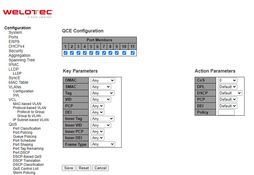
Table 2.97 Descriptions of QoS Control Entry’s Parameters:
Label |
Description |
Factory Default |
|---|---|---|
Port Members |
Check the checkbox button to include the port in the QCL entry. By default, all ports are included. |
All ports |
Key Parameters |
Key configuration is described as below:
|
Any |
Action Parameters |
CoS: Class of Service: (0-7) or ‘Default’. |
Default |
Table 2.98 Description of Frame Type:
Frame Type |
Description |
|---|---|
Any |
Allow all types of frames. |
EtherType |
Ether Type Valid Ether Type can be 0x600-0xFFFF excluding 0x800(IPv4) and 0x86DD(IPv6) or ‘Any’. |
LLC |
DSAP Address Valid DSAP (Destination Service Access Point) can vary from 0x00 to 0xFF or ‘Any’. |
SNAP |
PID Valid PID (a.k.a Ether Type) can be 0x0000-0xFFFF or ‘Any’. |
IPv4 |
Protocol IP protocol number: (0-255, ‘TCP’ or ‘UDP’) or ‘Any’. |
IPv6 |
Protocol IP protocol number: (0-255, ‘TCP’ or ‘UDP’) or ‘Any’. |
Click Save button to save the configuration and move to main QCL page. Click Reset button to undo any changes made locally and revert to previously saved values. Click Cancel button to return to the previous page without saving the configuration change.
Storm Policing
Global storm policers for the managed switch are configured on this webpage as shown in Figure 2.109. There are unicast storm policer, multicast storm policer, and broadcast storm policer. These only affect flooded frames, i.e., frames with a (VLAN ID, DMAC) pair not present in the MAC Address table. The settings are described in Table 2.99.
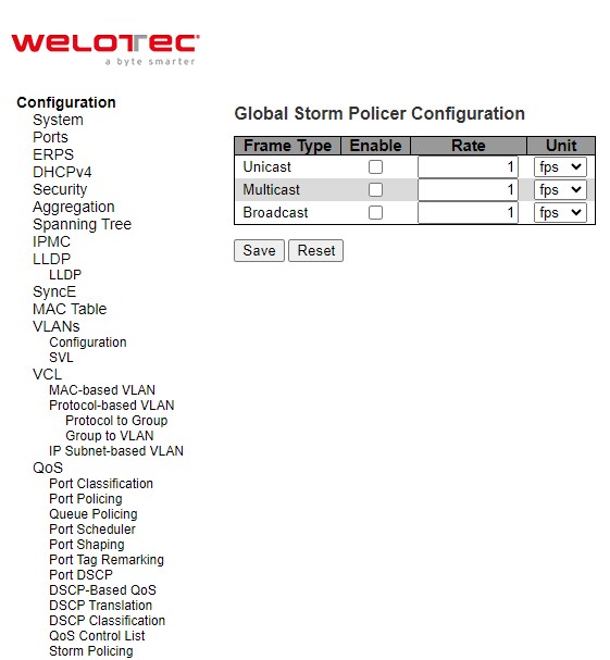
Table 2.99 Descriptions of Storm Policing Configuration of QoS:
Label |
Description |
Factory Default |
|---|---|---|
Frame Type |
The frame type for which the configuration below applies. |
- |
Enable |
Enable or disable the global storm policer for the given frame type. |
Unchecked |
Rate |
Controls the rate for the global storm policer. This value is restricted to 1-1024000 when “Unit” is fps, and 1-1024 when “Unit” is kfps. The rate is internally rounded up to the nearest value supported by the global storm policer. Supported rates are 1, 2, 4, 8, 16, 32, 64, 128, 256 and 512 fps for rates <= 512 fps and 1, 2, 4, 8, 16, 32, 64, 128, 256, 512 and 1024 kfps for rates > 512 fps. |
1 |
Unit |
Controls the unit of measure for the global storm policer rate as fps or kfps. |
fps |
Click Save button to save the setting configuration. Click Reset button to undo any changes made locally and revert to previously saved values.
Mirroring
In order to help the network administrator keeps track of network activities, the managed switch supports port mirroring, which allows incoming and/or outgoing traffic to be monitored by a single port that is defined as a mirror port. Note that the mirrored network traffic can be analysed by a network analyser or a sniffer for network performance or security monitoring purposes. Figure 2.111 shows the Mirror Port webpage. The descriptions of port mirroring options are summarized in Table 2.100.
Port mirroring or traffic mirroring enables users to monitor network traffic passing in, or out of, a set of ports. can then pass this traffic to a destination port on the same router. Traffic mirroring copies traffic from one or more source ports and sends the copied traffic to one or more destinations for analysis by a network analyser or other monitoring device. However, traffic from one source port can be copied to only one destination port. Traffic mirroring does not affect the flow of traffic on the source ports, and allows the mirrored traffic to be sent to a destination port. For example, you need to attach a traffic analyser to the router if you want to capture Ethernet traffic that is sent by host A to host B. Traffic between host A and host B is also seen on the destination port.
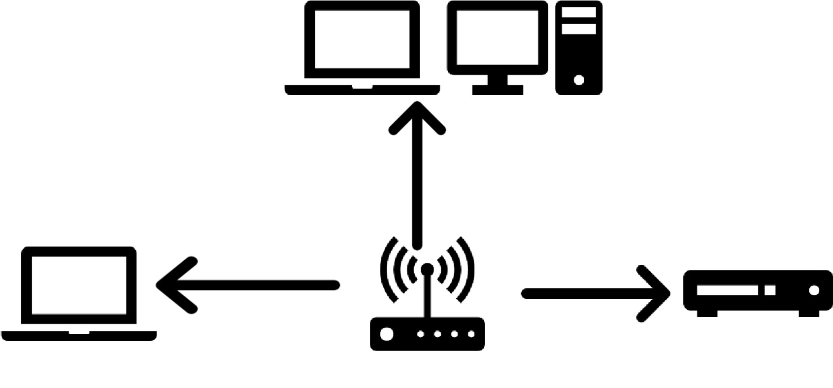
When local traffic mirroring is enabled, the traffic analyser is attached directly to the port of the same router that is configured to receive a copy of every packet that host A sends. This port is called a traffic mirroring port. The other sections of this document describe how you can fine tune this feature.
The following types of traffic mirroring are supported:
Local traffic mirroring: This is the most basic form of traffic mirroring. The network analyzer orsniffer is directly attached to the destination interface. In other words, all monitored ports are all located on the same router as the destination port.
Layer 2 or Layer 3 traffic mirroring: Both Layer 2 and Layer 3 source ports can be mirrored.
Mirroring is a feature for switched port analyzer. The administrator can use the Mirroring to debug network problems. The selected traffic can be mirrored or copied on a destination port where a network analyzer can be attached to analyze the network traffic. Remote Mirroring is an extend function of Mirroring. It can extend the destination port in other switch so that the administrator can analyze the network traffic on the other switches. If you want to get the tagged mirrored traffic, you have to set VLAN egress tagging as “Tag All” on the reflector port. On the other hand, if you want to get untagged mirrored traffic, you have to set VLAN egress tagging as “Untag ALL” on the reflector port.
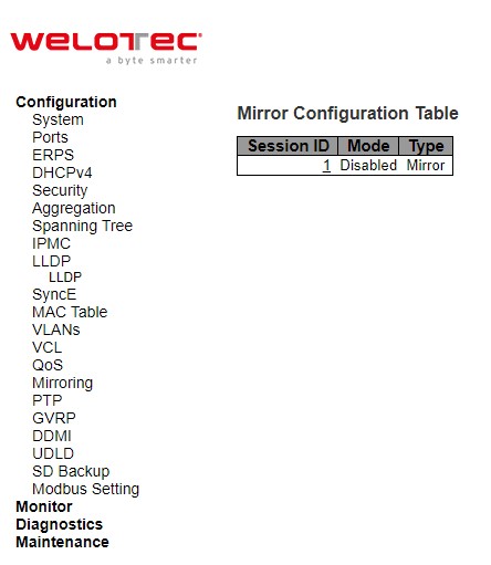
Table 2.100 Descriptions of Mirroring Webpage
Label |
Description |
Factory Default |
|---|---|---|
Session ID |
Display Mirror feature session id. |
1 |
Mode |
To Enabled/Disabled the Mirroring function. |
Disabled |
Type |
Display switch mirroring type. |
Mirror |
VLAN ID |
The VLAN ID points out where the monitor packet will copy to. The default VLAN ID is 200. |
- |
Port Configuration |
Port: The logical port for the settings contained in the same row. |
- |
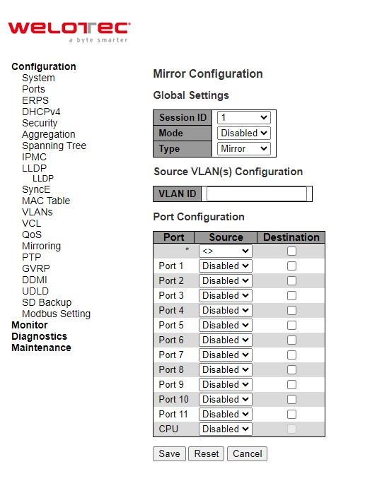
PTP
Precision Time Protocol (PTP) is defined in IEEE 1588 as Precision Clock Synchronization for Networked Measurements and Control Systems, and was developed to synchronize the clocks in packet-based networks that include distributed device clocks of varying precision and stability. PTP, which is a high-precision time protocol, can be used with measurement and control systems in local area network that require precise time synchronization. PTP is designed specifically for industrial, networked measurement and control systems, and is optimal for use in distributed systems because it requires minimal bandwidth and little processing overhead. Smart grid power automation applications such as peak-hour billing, virtual power generators, and outage monitoring and management, require extremely precise time accuracy and stability. Timing precision improves network monitoring accuracy and troubleshooting ability. In addition to providing time accuracy and synchronization, the PTP message-based protocol can be implemented on packetbased networks, such as Ethernet networks. The benefits of using PTP in an Ethernet network include:
Low cost and easy setup in existing Ethernet networks
Limited bandwidth is required for PTP data packets
In an Ethernet network, switches provide a full-duplex communication path between network devices. Switches send data packets to packet destinations using address information contained in the packets. When the switch attempts to send multiple packets simultaneously, some of the packets are buffered by the switch so that they are not lost before they are sent. When the buffer is full, the switch delays sending packets. This delay can cause device clocks on the network to lose synchronization with one another. Additional delays can occur when packets entering a switch are stored in local memory while the switch searches the MAC address table to verify packet CRC fields. This process causes variations in packet forwarding time latency, and these variations can result in asymmetrical packet delay times. Adding PTP to a network can compensate for these latency and delay problems by correctly adjusting device clocks so that they stay synchronized with one another. PTP enables network switches to function as PTP devices, including boundary clocks (BCs) and transparent clocks (TCs). To ensure clock synchronization, PTP requires an accurate measurement of the communication path delay between the time source or primary clock and the client clock. The system clocks can be categorized based on the role of the node in the network. They are broadly categorized into ordinary clocks and boundary clocks. The primary clock and the client clock are known as ordinary clocks. The boundary clock can operate as either a primary clock or a client clock. The following list explains these clocks in detail:
Primary clock—The primary clock transmits the messages to the PTP clients (also called client node or boundary node). This allows the clients to establish their relative time distance and offset from the primary clock (which is the reference point) for phase synchronization. Delivery mechanism to the clients is either unicast or multicast packets over Ethernet or UDP.
Member clock—located in the PTP client (also called client node), the client clock performs clock and time recovery operations based on the received and requested timestamps from the primary clock.
Boundary clock—The boundary clock operates as a combination of the primary and client clocks. The boundary clock endpoint acts as a client clock to the primary clock, and also acts as the primary to all the slaves reporting to the boundary endpoint.
PTP sends messages between the primary clock and client clock device to determine the delay measurement. Then, PTP measures the exact message transmit and receive times and uses these times to calculate the communication path delay. PTP then adjusts current time information contained in network data for the calculated delay, resulting in more accurate time information. This delay measurement principle determines path delay between devices on the network, and the local clocks are adjusted for this delay using a series of messages sent between masters and slaves. The one-way delay time is calculated by averaging the path delay of the transmit and receive messages. This calculation assumes a symmetrical communication path; however, switched networks do not necessarily have symmetrical communication paths, due to the buffering process. PTP provides a method, using transparent clocks, to measure and account for the delay in a time-interval field in network timing packets, making the switches temporarily transparent to the master and slave nodes on the network. An end-to-end transparent clock forwards all messages on the network in the same way that a switch does.
The PTP webpage as shown in Figure 2.113 allows the user to configure and inspect the current PTP clock settings. Table 2.101 summarizes the parameters for PTP Clock Configuration.
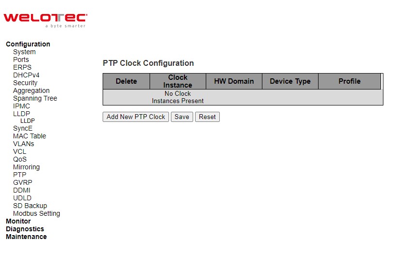
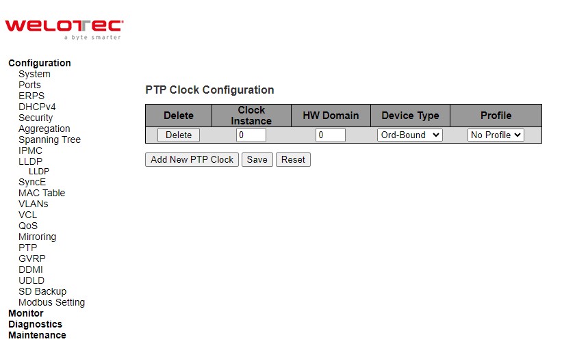
Table 2.101 Descriptions of PTP Clock Configuration:
Label |
Description |
Factory Default |
|---|---|---|
Delete |
Check this box and click on ‘Save’ button to delete the clock instance. |
- |
Clock Instance |
Indicates the Instance of a particular Clock Instance [0…3]. Click on the Clock Instance number to edit the Clock details. |
|
HW Domain |
Indicates the HW clock domain used by the clock. |
|
Device Type |
Indicates the Type of the Clock Instance. There are five Device Types.
|
|
Profile |
Indicates the profile used by the clock. |
After Clicking Add NEW PTP Clock button, another webpage will be launched, as shown in Figure 2.114. Table 2.102 summarizes the parameters for new PTP Clock Configuration.
Table 2.102 Descriptions of New PTP Clock Configuration:
Label |
Description |
Factory Default |
|---|---|---|
Delete |
Check this box and click on ‘Save’ to delete the clock instance. |
- |
Clock Instance |
Indicates the instance number of a particular Clock Instance [0..3]. |
0 |
HW Domain |
Indicates the HW clock domain used by the clock. |
0 |
Device Type |
Indicates the Type of the Clock Instance. There are five Device Types.
|
Ord-bound |
Profile |
Indicates the profile used by the clock. |
No Profile |
Click Add New PTP Clock button to create a new clock instance. Click Save button to save the setting configuration. Click Reset button to keep to the original setting.
GVRP
GVRP (GARP VLAN Registration Protocol or Generic VLAN Registration Protocol) is a standard-based protocol that facilitates control of virtual local area networks (VLANs) within a larger network. GVRP conforms to the Institute of Electrical and Electronics Engineers (IEEE) 802.1Q specification, which defines a method of tagging frames with VLAN configuration data over networ trunk interconnects. GVRP is based on Generic Attribute Registration Protocol (GARP) and IEEE 802.1r, which defines procedures for end stations and switches in a VLAN to register and deregister attributes, such as identifiers or addresses, with each other. It provides every end station and switch with a current record of all the other end stations and switches that can be reached on the network. GVRP is similar to GARP, as both eliminate unnecessary network traffic by preventing attempts to transmit information to unregistered users. In addition, it is necessary to manually configure only one switch with all the other switches then being updated automatically.
Becoming part of a formal IEEE 802.1ak standard amendment in 2007, Multiple VLAN Registration Protocol replaced GVRP, as it was found to be prone to performance issues that could potentially cause prolonged network convergence. This delay was found to create bandwidth degradation on the network at the point where the delayed convergence appeared. Technically, GVRP is still included as part of the IEEE standard, as the amendment did not completely remove it. It is expected to be removed in the future, but until that happens, GVRP is still being used. GVRP can be used to keep VLAN configurations on trunk interfaces organized across the network on large networks that consist of dozens or even hundreds of VLAN segments. There are three benefits for administrators that enable GVRP on a network:
It enables switches to automatically delete unused VLANs so that only the VLANs that are in use are transported across 802.1Q trunk links.
It enables admins to configure a new VLAN on one switch and then have it propagate the configuration across all network switches participating in the GVRP process.
GVRP can eliminate some unnecessary broadcast traffic on the network, reducing bandwidth overhead used for network management.
GVRP works as follows. When two or more switches are connected via 802.1Q trunk ports with GVRP enabled in a network, these switches will begin to communicate statically or dynamically through VLAN information. Switches with statically configured VLANs will advertise them to connected switches using GVRP data units. Those units are specifically designed management packets used to share VLAN information. If a switch learns of a new VLAN from its neighbor, this VLAN is added to the list of VLAN tags that can be transported across the link The VLAN that learned the new information can then pass along its own statically configured VLANs, in addition to ones learned from its neighbor. For loop avoidance, switch cannot send dynamically learned VLAN information out the same interface that it was learned on. All the dynamically learned VLAN information is stored in switch memory. So, if power is lost or the switch is rebooted, the dynamically learned VLAN information is lost, and the VLANs are pruned from the trunk interface. But, once the switches begin communication again, they will relearn the shared VLAN information to bring the network and all VLANs back into a fully informed state.
Global config
This GVRP⭢Global config webpage shown in Figure 2.115 allows the user to configure the global GVRP configuration settings that are commonly applied to all GVRP enabled ports.
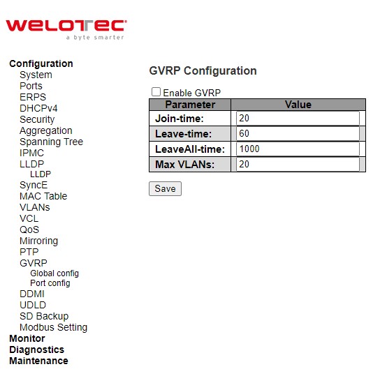
Table 2.103 Descriptions of GVRP Globally Configuration:
Label |
Description |
Factory Default |
|---|---|---|
Join-time |
Join-time is a value in the range of 1-20cs, i.e. in units of one hundredth of a second. The default value is 20cs |
20 |
Leave-time |
Leave-time is a value in the range of 60-300cs, i.e. in units of one hundredth of a second. The default is 60cs. |
60 |
LeaveAll-time |
LeaveAll-time is a value in the range of 1000-5000cs, i.e. in units of one hundredth of a second. The default is 1000cs. |
1000 |
Max VLANs |
When GVRP is enabled, a maximum number of VLANs supported by GVRP is specified. By default, this number is 20. This number can only be changed when GVRP is turned off. |
20 |
Click Save button to save the setting configuration. Click Refresh box to refresh the page immediately. Note that unsaved changes will be lost.
Port config
The GVRP Port Config webpage shown in Figure 2.116 allows the user to enable or disable a port for GVRP operation. This configuration can be performed either before or after GVRP is configured globally; however, the protocol operation will remain the same. Table 2.104 describes the labels on GVRP Port Configuration.
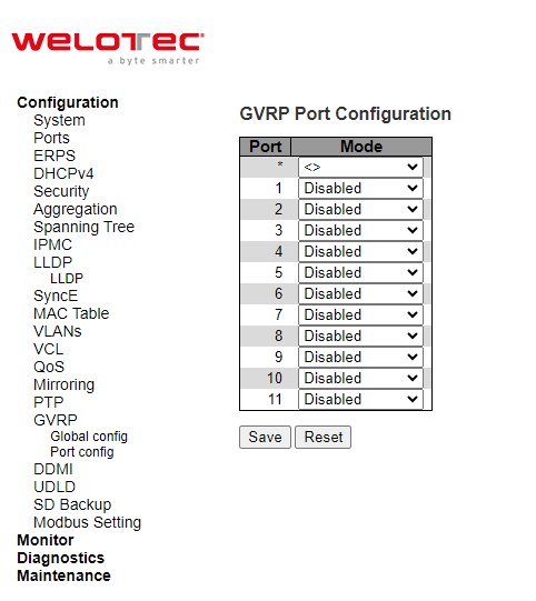
Table 2.104 Descriptions of GVRP PortConfiguration:
Label |
Description |
Factory Default |
|---|---|---|
Port |
The logical port that is to be configured. |
- |
Mode |
Mode can be either ‘Disabled’ or ‘GVRP enabled’. These values turn the GVRP feature off or on respectively for the port in question. |
Disabled |
Click Save button to save the setting configuration. Click Reset button to undo any changes made locally and revert to previously saved values.
DDMI
Digital Diagnostics Monitoring Interface (DDMI) allows users to perform diagnostic tests on transceiver modules such as small form-factor pluggable (SFP). Click Enabled this feature to view the various parameters of the transceiver module, such as temperature, voltage, transmission power, and so on. Figure 2.117 shows the DDMI configuration webpage. Table 2.105 describes the option on DDMI Configuration webpage.
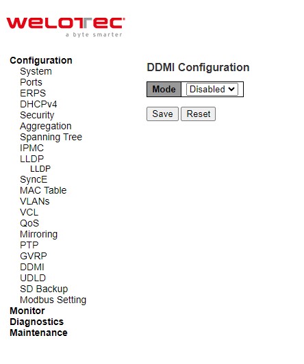
Table 2.105 Descriptions of DDMI Configuration:
Label |
Description |
Factory Default |
|---|---|---|
Mode |
Indicates the DDMI mode operation. Possible modes are: |
Disabled |
Click Save button to save changes. Click Reset button to undo any changes made locally and revert to previously saved values.
UDLD
Unidirectional Link Detection (UDLD) is a layer 2 protocol used to determine the physical status of a link. The purpose of UDLD is to detect and deter issues that arise from Unidirectional Links. UDLD helps to prevent forwarding loops and blackholding of traffic by identifying and acting on logical one-way links that would otherwise go undetected. UDLD works with the Layer 1 mechanisms to determine the physical status of a link. At Layer 1, auto-negotiation takes care of physical signaling and fault detection. UDLD performs tasks that auto-negotiation cannot perform, such as detecting the identities of neighbors and shutting down misconnected ports. When users enable both auto-negotiation and UDLD, Layer 1 and Layer 2 detections work together to prevent physical and logical unidirectional connections and the malfunctioning of other protocols.
UDLD works by exchanging UDLD protocol packets that include information about the port’s device and port ID between the neighboring devices. In order for UDLD to work, both devices on the link must support UDLD and have it enabled on respective ports. Each switch port configured for UDLD sends UDLD protocol packets that contain the port’s own device/port ID, and the neighbor’s device/port IDs seen by UDLD on that port. Neighboring ports should see their own device/port ID (echo) in the packets received from the other side.
Because of this, a port should receive its own device and port ID information from its neighbor if the link is bi-directional. If a port does not receive information about its own device and port ID from its neighbor for a specific duration of time, the link is considered to be unidirectional. This can also occur when the link is up on both sides, but one side is not receiving packets, or when wiring mistakes occur, causing the transmit and receive wires to not be connected to the same ports on both ends of a link.
This echo-algorithm allows detection of these issues:
Link is up on both sides; however, packets are only received by one side.
Wiring mistakes when receive and transmit fibers are not connected to the same port on the remote side.
Once the unidirectional link is detected by UDLD, the respective port is disabled. Port shutdown by UDLD remains disabled until it is manually reenabled, or until errdisable timeout expires (if configured).
UDLD can operate in two modes: normal and aggressive. In normal mode, if the link state of the port was determined to be bidirectional and the UDLD information times out, no action is taken by UDLD. The port state for UDLD is marked as undetermined. The port bRSAESaves according to its STP state. In aggressive mode, if the link state of the port is determined to be bi-directional and the UDLD information times out while the link on the port is still up, UDLD tries to re-establish the state of the port. If not successful, the port is put into the errdisable state.
Aging of UDLD information happens when the port that runs UDLD does not receive UDLD packets from the neighbor port for duration of hold time. The hold time for the port is dictated by the remote port and depends on the message interval at the remote side. The shorter the message interval, the shorter the hold time and the faster the detection. Recent implementations of UDLD allow configuration of message interval.
UDLD information can age out due to the high error rate on the port caused by some physical issue or duplex mismatch. Such packet drop does not mean that the link is unidirectional and UDLD in normal mode will not disable such link.
It is important to be able to choose the right message interval in order to ensure proper detection time. The message interval should be fast enough to detect the unidirectional link before the forwarding loop is created, however, it should not overload the switch CPU. The default message interval is 7 seconds, and is fast enough to detect the unidirectional link before the forwarding loop is created with default STP timers. The detection time is approximately equal to three times the message interval.
For example: T~detection~ ~ message_interval x 3 This is 21 seconds for the default message interval of 7 seconds.
It takes T~reconvergence~=max_age + 2x forward_delay for the STP to reconverge in case of unidirectional link failure. With the default timers, it takes 20+2x7=34 seconds.
It is recommended to keep T~detection~ < T~reconvergence~ by choosing an appropriate message interval.
In aggressive mode, once the information is aged, UDLD will attempt to re-establish the link state by sending packets every second for eight seconds. If the link state is still not determined, the link is disabled.
Aggressive mode adds additional detection of these situations:
The port is stuck (on one side the port neither transmits nor receives, however, the link is up on both sides).
The link is up on one side and down on the other side. This is issue might be seen on fiber ports. When transmit fiber is unplugged on the local port, the link remains up on the local side. However, it is down on the remote side.
Most recently, fiber FastEthernet hardware implementations have Far End Fault Indication (FEFI) functions in order to bring the link down on both sides in these situations. On Gigabit Ethernet, a similar function is provided by link negotiation. Copper ports are normally not susceptible to this type of issue, as they use Ethernet link pulses to monitor the link. It is important to mention that, in both cases, no forwarding loop occurs because there is no connectivity between the ports. If the link is up on one side and down on the other, however, blackholing of traffic might occur. Aggressive UDLD is designed to prevent this.
This UDLD webpage shown Figure 2.118 allows the user to inspect the current UDLD configurations, and possibly change them as well. Table 2.106 provides the descriptions of UDLD Port Configuration.
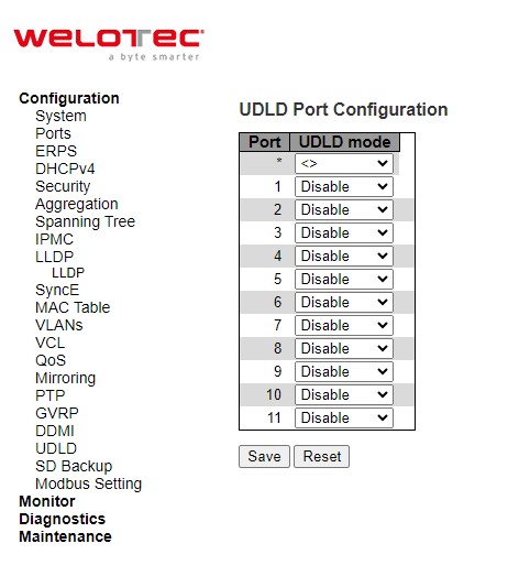
Table 2.106 Descriptions of UDLD Port Configuration:
Label |
Description |
Factory Default |
|---|---|---|
Port |
Port number of the switch. |
1-11 |
UDLD Mode |
Configures the UDLD mode on a port. Valid values are Disable, Normal and Aggressive. Default mode is Disable.
|
Disable |
Click Save button to save the setting configuration. Click Reset button to undo any changes made locally and revert to previously saved values.
SD Backup
The SD card can be used instead of the internal flash memory of the switch to update or restore configuration settings. In addition, the SD card can be used to boot the switch. User can also copy IOS software and switch configuration settings from a PC or from the switch to the SD card, and then use the SD card to copy this software and settings to other switches.
SD Backup can be configured on this page as shown in Figure 2.119. Options for SD Backup can be set according to the descriptions in Table 2.107.
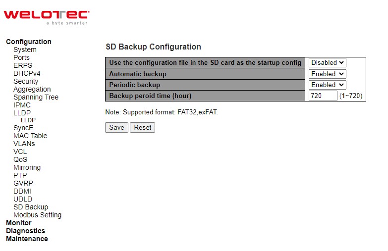
Table 2.107 Descriptions of SD Backup Configuration:
Label |
Description |
Factory Default |
|---|---|---|
Use the configuration file form sd |
The startup-config file will be replaced from the newest config file in sd card when booting switch. |
Disabled |
Automatic backup |
Backup the starup-config into sd card folder “Automatic_backup” when saving startup-config. Only have one file be saved. |
Enabled |
Periodic backup |
Backup the starup-config into sd card folder “Period_backup” when saving startup-config. Multiple files can be saved which depend on “Backup period time”. |
Enabled |
Backup period time (Hr) |
The backup Periodic time setting. |
720 |
Click Save button to save the setting configuration. Click Reset button to undo any changes made locally and revert to previously saved values.
Modbus Setting
Welotec’s managed switch can be connected to a Modbus network using Modbus TCP/IP protocol which is an industrial network protocol for controlling automation equipment. The managed switch’s status and settings can be read and written through Modbus TCP/IP protocol which operates similar to a Management Information Base (MIB) browser. The managed switch will be a Modbus slave which can be remotely configured by a Modbus master. The Modbus slave address must be set to match the setting inside the Modbus master. In order to access the managed switch, a Modbus Address must be assigned as described in this subsection. Figure 2.120 shows the Modbus Setting webpage.
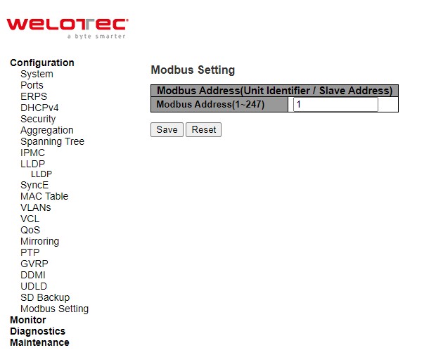
Table 2.108 Descriptions of Modbus Setting PortConfiguration:
Label |
Description |
Factory Default |
|---|---|---|
Modbus Address |
Identifier for modbus slave device, range from 1 to 247 |
1 |
Click Save button to save the setting configuration. Click Reset button to undo any changes made locally and revert to previously saved values.
Users can use Modbus TCP/IP compatible applications such as Modbus Poll to configure the switch. Note that Modbus Poll can be download from http://www.modbustools.com/download.html. The Modbus Poll 64-bit version 9.2.2, Build 1343 was used in this document. Welotec does not provide this software to the users. Tutorial of Modbus read and write examples are illustrated below. Note:** The switch only supports Modbus function code 03, 04 (for Read) and 06 *(for Write).
Read Registers (This example shows how to read the switch’s IP address.)
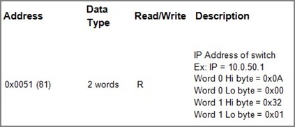
Make sure that a supervising computer (Modbus Master) is connected to your target switch (Modbus Slave) over Ethernet network.
Launch Modbus Poll in the supervising computer. Note a registration key may be required for a long-term use of Modbus Poll after 30-day evaluation period. Additionally, there is a 10-minute trial limitation for the connection to the managed switch.
Click Connect button on the top toolbar to enter Connection Setup dialog by selecting Connect… menu as shown in Figure 2.120
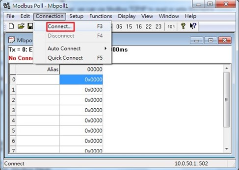
Select Modbus TCP/IP as the Connection mode and enter the switch’s IP address inside the Remote Modbus Server’s IP Address or Node Name field at the bottom as shown in Figure 2.121. The Port number should be set to 502. Then click OK button.
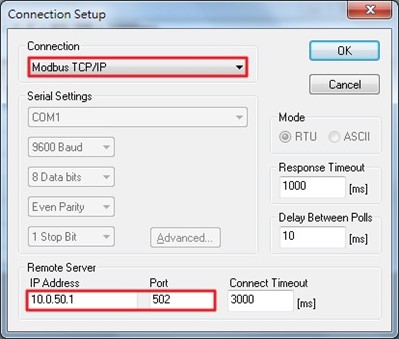
On the window Mbpoll1, select multiple cells from row 0 to row 2 by clicking on cells in second column of row 0 and row 2 while holding the shift key as shown in Figure 2.122.
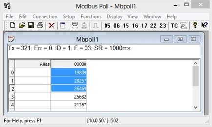
Set Display mode of the selected cells in previous step to HEX (hexadecimal) by selecting Display pull-down menu and choosing the Hex as shown in Figure 2.123.
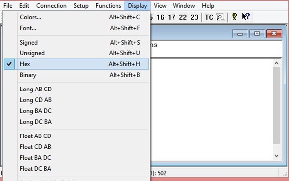
Click on the Setup pull-down menu and choose Read/Write Definition… as shown in Figure 2.124.
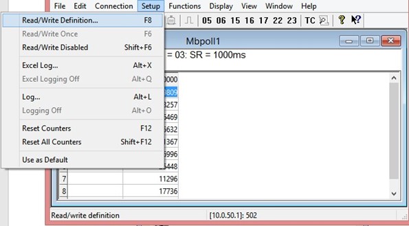
Enter the Slave ID in the Modbus Poll function as shown in Figure 2.125, which should match the Modbus Address = 1 entered in Figure 2.118.
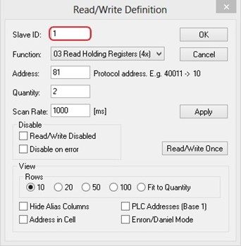
Select Function 03 or 04 because the managed switch supports function code 03 and 04 as shown in Figure 2.126.
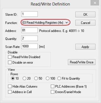
Set starting Address to 81 and Quantity to 2 as shown in Figure 2.127.
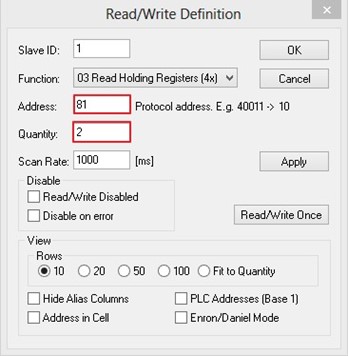
Click OK button to read the IP address of the switch.
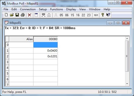
Modbus Poll will get the values 0x0A, 0x00, 0x32, 0x01, which means that the switch’s IP is 192.168.2.1 as shown in Figure 2.128.
Write Registers (This example shows how to clear the switch’s Port Count (Statistics).)
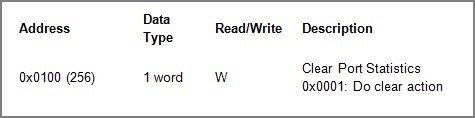
Check the switch’s Port TX/RX counts in Port Statistics page as shown in Figure 2.130.
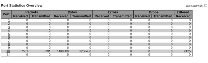
Click function 06 on the toolbar as shown in Figure 2.131.
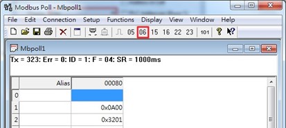
Set Address to 256 and Value (HEX) to 1 as shown in Figure 2.132, then click “Send” button.
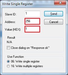
Check Port Statistics in the managed switch’s Web UI as shown in Figure 2.133. The packet count is now cleared.
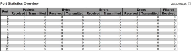
Modbus Memory Map
Read Registers (Support Function Code 3, 4).
Write Register (Support Function Code 6).
1 Word = 2 Bytes.
Address |
Data Type |
Read/Write |
Description |
|---|---|---|---|
System Information |
|||
0x0000 (0) |
32 words |
R |
System Description = “Managed Switch RSAES” |
0x0020 (32) |
1 word |
R |
Firmware Version = |
0x0021 (33) |
3 words |
R |
Ethernet MAC Address |
0x0024 (36) |
1 word |
R |
Kernel Version |
Console Information |
|||
0x0030 (48) |
32 words |
R |
Baud Rate |
0x0031 (49) |
1 word |
R |
Data Bits |
0x0032 (50) |
1 word |
R |
Parity |
0x0033 (51) |
1 word |
R |
Stop Bit |
0x0034 (52) |
1 word |
R |
Flow Control |
Power Information |
|||
0x0040 (64) |
1 word |
R |
Power Status |
IP Information |
|||
0x0050 (80) |
1 word |
R |
DHCP Status |
0x0051 (81) |
2 words |
R |
IP Address of switch |
0x0053 (83) |
2 words |
R |
Subnet Mask of switch |
0x0055 (85) |
2 words |
R |
Gateway Address of switch |
0x0057 (87) |
2 words |
R |
DNS1 of switch |
0x0059 (89) |
2 words |
R |
DNS2 of switch |
System Status Clear |
|||
0x0100 (256) |
1 word |
W |
Clear Port Statistics |
0x0101 (257) |
1 word |
W |
Clear Relay Alarm |
Port Status |
|||
0x1000 (4096) |
5 words |
R |
Port Status |
0x1020 (4128) |
5 words |
R |
Port Negotiation |
0x1040 (4160) |
5 words |
R |
Port Speed |
0x1060 (4192) |
5 words |
R |
Port Duplex |
0x1080 (4224) |
5 words |
R |
Port Flow Control |
0x10A0 (4256) |
5 words |
R |
Port Link Status |
0x1300 (4864) |
40 words |
R |
Count of Good Packets of TX |
0x1400 (5120) |
40 words |
R |
Count of Bad Packets of TX |
0x1500 (5376) |
40 words |
R |
Count of Good Packets of RX |
0x1600 (5632) |
40 words |
R |
Count of Bad Packets of RX |